Proservo NMS81
18 Endress+Hauser
I/O modules Overview
E
G
F
1
1
1
1 3
2
2
2 4
HR
CDI
WP
on
SIM
POWER
i
D
C
B
A
1
1
2
2
3
3
4
4
1
1
2
2
3
3
4
4
5
5
6
6
7
7
8
8
D
E
F
C
B
A
1
1
1
1 3
2
2 4
1
HR
CDI
WP
on
SIM
2
2
3
3
4
4
1
1
2
2
3
3
4
4
5
5
6
6
7
7
8
8
i
G
1
3
2
POWER
A0027363
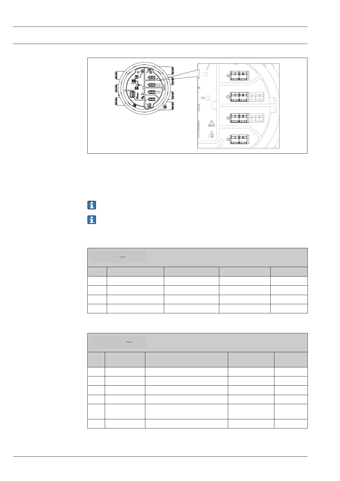
8 Position of the I/O modules in the terminal compartment
The terminal compartment contains up to four I/O modules, depending on the order code.
• Modules with four terminals can be in any of these slots.
• Modules with eight terminals can be in slot B or C.
The exact assignment of the modules to the slots is dependent on the device version. For a
detailed description refer to the Operating Instructions of the device in question.
The following restrictions apply when selecting the modules:
• The device may contain a maximum of four I/O modules.
• A maximum of two I/O modules with 8 terminals is possible.
Ordering feature 040: "Primary Output"
NMx8x - XX xx xxxxxx ...
040
Option Number of I/O modules Type of I/O module Number of terminals Technical data
A1 1 Modbus RS485 4 → 19
B1 1 V1 4 → 20
E1 1 4-20mA HART Ex d/XP 8 → 21
H1 1 4-20mA HART Ex i/IS 8 → 21
Ordering feature 050: "Secondary IO Analogue"
NMx8x - xx XX xxxxxx ...
050
Option Number of I/O
modules
Type of I/O module Number of terminals Technical data
A1 1 1 x "Ex d/XP 4-20mA HART + RTD input" 1 x 8 → 21
A2 2 2 x "Ex d/XP 4-20mA HART + RTD input" 2 x 8 → 21
B1 1 1 x "Ex i/IS 4-20mA HART+ RTD input" 1 x 8 → 21
B2 2 2 x "Ex i/IS 4-20mA HART+ RTD input" 2 x 8 → 21
C2 2 1 x "Ex i/IS 4-20mA HART + RTD input"
1 x "Ex d/XP 4-20mA HART + RTD input"
2 x 8 → 21
X0 0 none 0 -
 Loading...


