Proservo NMS81
24 Endress+Hauser
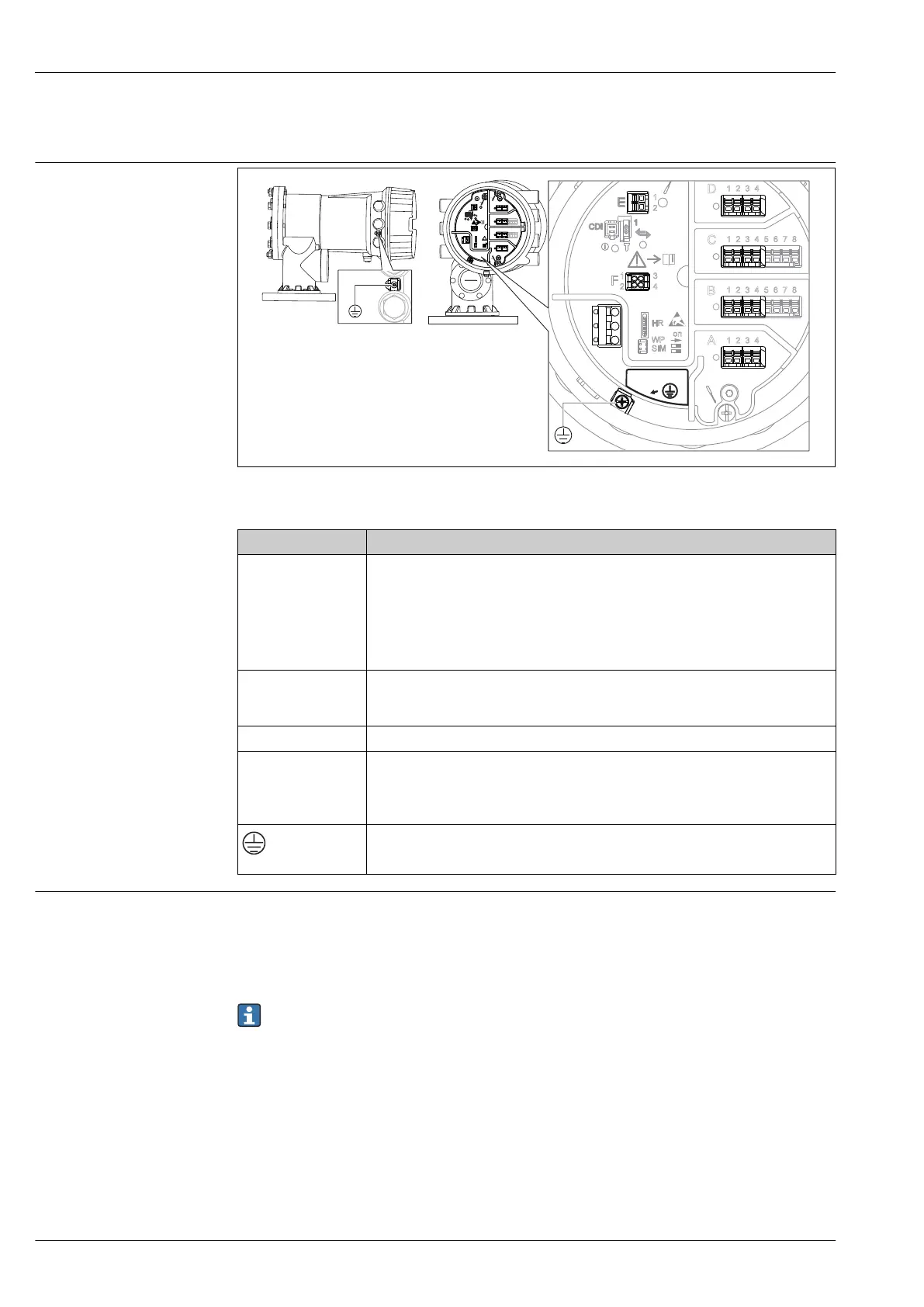
Power supply
Terminal assignment
D
E
G
F
C
B
A
1
1
1
1
1 3
2
2
2 4
1
HR
CDI
WP
on
SIM
2
2
3
3
4
4
1
1
2
2
3
3
4
4
5
5
6
6
7
7
8
8
POWER
i
D
E
F
C
B
A
1
1
1
1 3
2
2 4
1
HR
CDI
WP
on
SIM
2
2
3
3
4
4
1
1
2
2
3
3
4
4
5
5
6
6
7
7
8
8
i
G
1
3
2
POWER
G1 N
G3 L
AC 85...264 V
A0027012
11 Terminal compartment (typical example) and ground terminals
Terminal area Module
A/B/C/D
(slots for I/O modules)
Up to four I/O modules, depending on the order code
• Modules with four terminals can be in any of these slots.
• Modules with eight terminals can be in slot B or C.
The exact assignment of the modules to the slots is dependent on the device
version. For a detailed description refer to the Operating Instructions of the
device in question.
E HART Ex i/IS interface
• E1: H+
• E2: H-
F Remote display (in preparation)
G
Power supply: 85 to 264 V
AC
• G1: N
• G2: not connected
• G3: L
A0018339
Protective ground connection
Sources for gauge commands
Gauge commands can be sent via various sources.
• Displays or CDI (e.g. FieldCare)
• Digital input (e.g. switch)
• Fieldbus (Modbus, V1, HART)
The last received gauge command via any sources will be executed as usual.
During calibration, gauge commands are not accepted from any sources.
 Loading...


