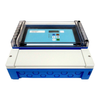
Prosonic S FMU90 Flow Measurement PROFIBUS Wiring
Endress+Hauser 17
Limitation of electrical safety.
‣ When using the public supply mains, an easily accessible power switch must be installed in
the proximity of the device. The power switch must be marked as a disconnector for the
device (IEC/EN 61010).
External switch inputs
71, 72, 73 External switch input 1 D 0: < 8 V or 72 and 73 interconnected
1: > 16 V or 72 and 73 not interconnected
74, 75, 76 External switch input 2 D 0: < 8 V or 75 and 76 interconnected
1: > 16 V or 75 and 76 not interconnected
77, 78, 79 External switch input 3 D 0: < 8 V or 78 and 79 interconnected
1: > 16 V or 78 and 79 not interconnected
80, 81, 82 External switch input 4 D 0: < 8 V or 81 and 82 interconnected
1: > 16 V or 81 and 82 not interconnected
Temperature input
83, 84, 85 Temperature input:
• PT100
• FMT131 (Endress+Hauser)
D → ä 21, "Connection of a temperature
sensor"
1) In this case, terminals 9/10/11 are not present on terminal area A.
In order to avoid interference, do not route the sensor cables parallel to high-voltage or
electric power lines and not close to frequency converters.
Terminals Meaning Terminal area Remarks

 Loading...


