RIA15 Product description
Endress+Hauser 9
3 Product description
3.1 Function
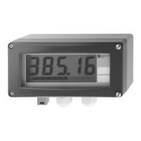
Process display unit RIA15 is integrated in the 4 to 20 mA/HART® loop and transmits the
measuring signal in digital form. The process display unit does not require an external
power supply. It is powered directly from the current loop.
In connection with the radar level sensor Micropilot FMR20, the RIA15 can be used to
make the basic settings for the Micropilot FMR20. As a prerequisite the RIA15 must be
ordered with the respective option for the FMR20 basic setting.
The device meets the requirements of the HART® Communication Protocol Specifications
and can be used with devices with HART® Revision ≥ 5.0.
3.2 Operating modes
The process display unit can be used in two different operating modes:
4 to 20 mA mode:
In this operating mode, the process display unit is incorporated into the 4 to 20 mA
current loop and measures the transmitted current. The variable calculated based on the
current value and range limits is displayed in digital form on the 5-digit LCD. In addition,
the associated unit and a bar graph can be displayed.
HART mode:
The device functions as a display unit even when operating with a HART® sensor/actuator.
In this case, the display is also powered from the current loop.
The process display unit can choose to function as a primary master or secondary master
(default) in the HART® loop. When it functions as a master, the device can read process
values from the measuring device and display them. HART® communication operates on
the principle of master/slave. As a general rule, the sensor/actuator is a slave and only
transmits information if a request has been made by the master.
A HART® loop can have a maximum of two HART® masters at any one time. A distinction
is made between primary (e.g. the control system) and secondary master (e.g. handheld
terminal for on-site operation of the measuring devices) for these HART® masters. The
two masters in the loop/in the network cannot be masters of the same type, e.g. they
cannot be two "secondary masters".
If a third HART® master is added to the network, one of the other masters must be
disabled; otherwise a collision occurs in the network.
If the process display unit is operating as "secondary master" and another "secondary
master", e.g. a handheld device, is added to the network, the device interrupts HART®
communication as soon as it detects that there is another "secondary master". The display
alternates between error message C970 "Multi master collision" and "- - -". A measured
value is not displayed in this case. The device leaves the HART® loop for 30 seconds and
tries to re-establish HART® communication once again. Once the additional "secondary
master" is removed from the network, the device continues communication and displays
the measured values of the sensor/actuator once more.
Please note that if two process display units are to be used in a multidrop connection,
one device must be configured as "primary master" and the other as "secondary master"
to prevent a master collision.
In HART mode, the process display unit can show up to four device variables of a
multivariable measuring device. These variables are referred to as the Primary Variable
(PV), Secondary Variable (SV), Tertiary Variable (TV) and Quaternary Variable (QV). These
variables are placeholders for measured values that can be called up using HART®
communication.
 Loading...