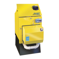
Frontier Gas Heat – PN 10-2027 – June 2018 11
Gas Heat System 2000 boilers and Type L gas vent must be installed in strict compliance with all State and Local
Codes and with the regulations of the authorities having jurisdiction, which may differ from and which take precedence over
these instructions or the vent manufacturer’s instructions.
B-VENT CHIMNEY
Gas Heat SYSTEM 2000 Boilers at factory default firing rates have flue gas temperatures between 350
o
F and 450
o
F
during normal operation. Refer to the burner settings table for the default firing rates. Due to the low flue gas
temperatures, Type B gas vent chimney pipe is suitable for use with Gas Heat SYSTEM 2000 Boilers. Type B gas vent
chimney pipe is double walled and may require smaller chase dimensions than other chimney pipe materials and should be
considered for new installations with Gas Heat SYSTEM 2000 Boilers.
A Type B gas vent system shall extend at least five (5) feet of height above the breech of the boiler.
Refer to the section on Gas Vent Termination in the National Fuel Gas Code to determine Minimum Height from Roof to
Lowest Discharge Opening required.
Type B gas vent must be U.L. Listed to U.L. 441. Type B gas vent to be installed and supported in accordance with the
vent manufacturer’s instructions.
Gas Heat System 2000 boilers and Type B gas vent must be installed in strict compliance with all State and Local
Codes and with the regulations of the authorities having jurisdiction, which may differ from and which take precedence over
these instructions or the vent manufacturer’s instructions.
SIDEWALL VENTING
1. System 2000 Boilers may be installed with Energy Kinetics' sidewall vent kit in accordance with kit instructions.
2.
WARNING: Sidewall vent systems must have outside air connected to the air box and both air box air intake and
vent hood must be located on the same side of the structure.
3. NOTICE: The sidewall vent inducer should be located above the boiler flue outlet, preferably a minimum of four feet
vertical distance, which will provide some natural draft to the boiler (and cooling of the burner) in case of a power
failure. When installing a sidewall venting system from another manufacturer, ensure that the manufacturer’s
instructions are followed. Vent manufacturer should confirm that the equipment is suitable for use with System 2000.
4. Set the draft at the over fire of the boiler to between -.10" to -.12" w.c. with the burner running, after allowing time for
sufficient warm-up. Check/adjust CO
2
. Re-check the draft at over fire and adjust draft if necessary.
5. To provide power to the sidewall vent, install the plug-in relay supplied with the sidewall vent kit into the junction box
relay board and set the Digital Manager Option Switch #2 to the “ON” (down) position. This enables the “Inducer” light
and allows the Digital Manager to control the inducer. Refer to Digital Manager section for option switch settings and
inducer timing details.
VENTING MATERIALS
Gas Heat SYSTEM 2000 Boilers at factory default firing rates generate exiting flue gas temperatures between 350
o
F
and 450
o
F during normal operation. The Frontier Gas boiler can be safely vented using a variety of venting materials.
Venting materials should be listed by a nationally recognized testing agency. Any venting material used must be at least
0.020” thickness. Approved materials include stainless steel, such as 316, 316L, 316Ti or AL 29-4C. For gas only
installations, aluminum is also approved. Plastic venting of any type, such as PVC, CPVC, ABS, or PP, is not approved.
Plastic pipe may be safely used for air intake piping, but not for venting.
REMOVAL FROM COMMON VENT SYSTEM
When any existing appliance, such as a boiler, is removed from a common venting system, the common venting system
is likely to be too large for proper venting of the appliances remaining connected to it. Testing of the remaining venting
system must be performed according to the following procedure.
At the time of removal of the existing appliance, the following steps shall be followed with each appliance remaining
connected to the common venting system placed in operation, while the other appliances remaining connected to the
common venting system are not in operation.
1. Seal any unused openings in the common venting system.
2. Visually inspect the venting system for proper size and horizontal pitch and determine there is no blockage or
restriction, leakage, corrosion and other deficiencies, which could cause an unsafe condition.
3. Insofar as is practical, close all building doors and windows and all doors between the space in which the appliances
remaining connected to the common venting system are located and other spaces of the building. Turn on clothes
dryers and any appliance not connected to the common venting system. Turn on any exhaust fans, such as range
hoods and bathroom exhausts, so they will operate at maximum speed. Do not operate a summer exhaust fan. Close
fireplace dampers.
4. Place in operation the appliance being inspected. Follow the lighting instructions. Adjust thermostat so appliance will
operate continuously.
5. Test for spillage after five minutes of main burner operation. Use a draft gauge or pressure gauge to verify that the
vent pipe at the breech of the appliance is under draft (negative pressure) relative to the room.
6. Repeat 4) and 5) for each appliance connected to the common venting system, one appliance at a time.
7. After it has been determined that each appliance remaining connected to the common venting system properly vents
when tested as outlined above, return doors, windows, exhaust fans, fireplace dampers and any other gas-burning
appliance to their previous condition of use.

 Loading...