Frontier Gas Heat – PN 10-2027 – June 2018 13
Gas piping must be properly sized in accordance with the National Fuel Gas Code, ANSI Z223.1/NFPA 54, or
according to state and local codes as applicable. Gas piping must be sized to provide the maximum firing rate gas flow for
all appliances in the building. For Natural Gas installations, be sure to verify that the gas meter is properly sized for all
appliances. Do not use any service 90
o
elbows. Use only full port shutoff valves. If in doubt, oversize the piping.
The following tables provide suggested sizing for Black Iron Pipe. Be sure to add the appropriate equivalent
length for every fitting and elbow used. For other types of pipe or tubing, consult NFPA 54 or the manufacturer
of the pipe or tubing or your gas supplier for pipe sizing information.
For LPG, drawing up to 150,000 Btu/Hr ( 60 Cubic Feet per Hour).
For Natural Gas, drawing up to 150,000 Btu/Hr ( 140 Cubic Feet per Hour).
Natural Gas LPG
Iron Pipe Size Maximum Equivalent
Length
Iron Pipe Size Maximum
Equivalent Length
1/2 inches 20 feet
3/4 inches 30 feet 3/4 inches 90 feet
1 inch 100 feet 1 inch 200 feet
1-1/4 inches 200 feet 1-1/4 inches 200 feet
For LPG, drawing up to 250,000 Btu/Hr (100 Cubic Feet per Hour).
For Natural Gas, drawing up to 250,000 Btu/Hr (250 Cubic Feet per Hour).
Natural Gas LPG
Iron Pipe Size Maximum Equivalent
Length
Iron Pipe Size Maximum
Equivalent Length
3/4 inches 10 feet 3/4 inches 20 feet
1 inch 40 feet 1 inch 90 feet
1-1/4 inches 150 feet 1-1/4 inches 200 feet
GENERAL ASSEMBLY
Assembly of various packaged units is illustrated throughout this manual. The use of non-Energy Kinetics supplied
pump, controls and accessories should follow good practices. The diagrams and locations presented in the manual are
recommended. WARNING: Boiler shall be installed such that the gas ignition system components are protected from
water (dripping, spraying, rain, etc.) during appliance operation and service (circulator replacement, control replacement,
etc.).
BOILER MOUNTING
BOILER PITCH: The Frontier pressure vessel is manufactured with the rear ½ to 1 bubble higher to allow for proper air
removal. This pitch is carefully set at the factory when the boiler is built. Be sure to level the stand prior to mounting the
boiler on the stand. When the stand is level, the pitch is correct and the back of the boiler will be higher than the front. The
EK-1 Frontier is pitched 1/4" and the EK-2 Frontier is pitched 7/16".
BOILER MOUNTING on TANK STAND, Figure 2A: Ensure that the boiler is properly mounted to the stand using the
5/16” hardware provided. Bolts should face up so they cannot interfere with removal of the tank at a later time. Holes in
boiler legs must line up with holes in the tank stand.
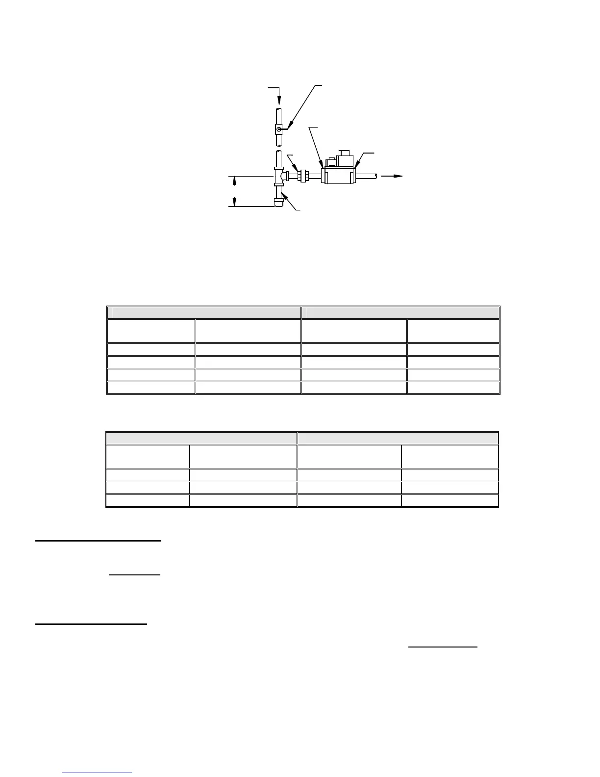
Inlet & Outlet on Valve
Manual Shutoff Valve
Height of Shutoff Valve above ground
level to conform to any local codes.
Union
Sediment Trap/Drip Leg
3" Min
Check for gas leaks, using a gas
detector or applying a leak detection
solution to any connections.
Direction of flow
Gas
Valve
Test Gauge Port -Inlet 1/8"NPT
Inlet Pressure 5" W.C. Min.
Test Gauge Port -Outlet 1/8" NPT
 Loading...


