Frontier Gas Heat – PN 10-2027 – June 2018 7
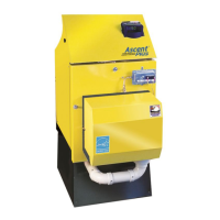
SYSTEM 2000
®
FRONTIER BOILER
IMPORTANT MESSAGE TO HOMEOWNER: These instructions should be carefully read and kept for future reference to
gain the best performance from your System 2000 Frontier boiler.
CONGRATULATIONS ON YOUR PURCHASE OF THE SYSTEM 2000 BOILER with its highly efficient low mass hydronic
heat exchanger, the Energy Converter. It is the product of years of engineering and advanced design, which brings
together in a single system all elements needed to provide efficient home heat. This operation and maintenance
information has been prepared so that you may better understand and use your Energy Kinetics Frontier Boiler and
Heating System.
SYSTEM 2000 BOILER - PRINCIPLE of OPERATION
SYSTEM 2000 comprises a heat source, the energy converter, circulating water and five (or more) zones controlled by an
electronic control, the Digital Manager.
The Boiler sits cold until a thermostat calls for heat. The Digital Manager receives the call for heat and turns on the
main circulator and burner. Water circulates within the boiler as it warms up to operating temperature. When ready, the
zone valves open and deliver heat to the zones calling for heat. When the thermostats are satisfied, the Digital Manager
turns off the burner and enters the energy recovery stage. The circulator and zone valve stay energized to deliver the heat
remaining in the boiler to your home.
When energy recovery is complete and the Boiler has been cooled off, the Digital Manager turns off the system and
waits for another thermostat (or tank aquastat) to call for heat. SYSTEM 2000 runs the burner only when you need heat
and delivers that heat only where you need heat.
The System 2000 Energy Converter is the product of advanced thermal engineering. It is designed with two separate
passageways, nearly 10 feet long, coiled around each other. Water travels along one passageway from your home toward
the center of the unit and heated gases travel from the unit center toward the chimney. This is a “forced circulation counter-
flow” design and it provides very efficient transfer of heat from the burning fuel to the circulating water. The superior
insulation of the boiler minimizes heat losses to the surroundings, resulting in directing heat to your home in an efficient and
quiet manner.
SYSTEM 2000 has an extremely high annual efficiency (over 99% of steady state) because it runs only when your
home needs heat. Energy recovery is completed at the end of each heat call, virtually eliminating off cycle losses.
Your System 2000 holds a minimal quantity of water so it begins to supply heat in about 90 seconds. This rapid
response means that your rooms can be heated quickly to temperature. The System 2000 EK-1 Frontier can heat water up
to 100,000 BTU’s per hour and the EK-2 Frontier up to 200,000 BTU/hr.
A modern power burner fires into the center of System 2000 where a high temperature, light weight ceramic chamber
provides ideal conditions for “near perfect” efficient, pollution-free combustion. Your System 2000 is tightly sealed so all
products of combustion pass only to the chimney.
The FRONTIER Boiler is designed with a hinged front cover that allows access to the inside of the boiler for inspection
and cleaning. All access for service is from the front, so the FRONTIER Boiler can be placed directly against a wall or into
a closet.
DIGITAL MANAGER - PRINCIPLE of OPERATION
The left side of the Manager is the input side, which provides 24-volt power supply and connections for thermostats.
The right side is the output side, which starts the burner, circulator and zone valves or zone circulators. See photo of the
Manager on the cover.
Lights on the Digital Manager indicate what is calling for heat (left side) and (right side) lights indicate active zone(s),
burner operation and circulator operation. These function lights are an aid in servicing. The following is a typical cycle.
1. SYSTEM WAITING FOR A CALL: The boiler is turned off and sits cold, waiting until a call for heat. The blue power
light on the Manager is on.
2. CALL FOR HEAT: A room thermostat call starts the cycle. The thermostat light on the left side will turn on for that
zone.
3. PRE-HEAT: Output lights for the main circulator and burner turn on, the circulator starts, and the burner begins firing.
The boiler water circulates through the energy converter via the bypass line, heating up the water.
4. HEAT: Once the boiler water has heated up to 150
o
F (about 90 seconds), the Manager will turn on the zone output
light on the right side. The zone valve will open and hot water will flow to the zone needing heat. The burner runs as
long as there is a thermostat calling and as long as heat is being delivered to the zone. The burner may shut off if the
return temperature exceeds 170
o
F/190
o
F (RED burner light turns off) or if the high limit temperature is exceeded (RED
burner light stays on, but the high limit aquastat shuts the burner off).
5. ANOTHER CALL FOR HEAT: If another zone calls for heat while the burner is already running and the return
temperature is above 150
o
F, the zone output will turn on, immediately supplying heat to the zone.

 Loading...