Frontier Gas Heat – PN 10-2027 – June 2018 9
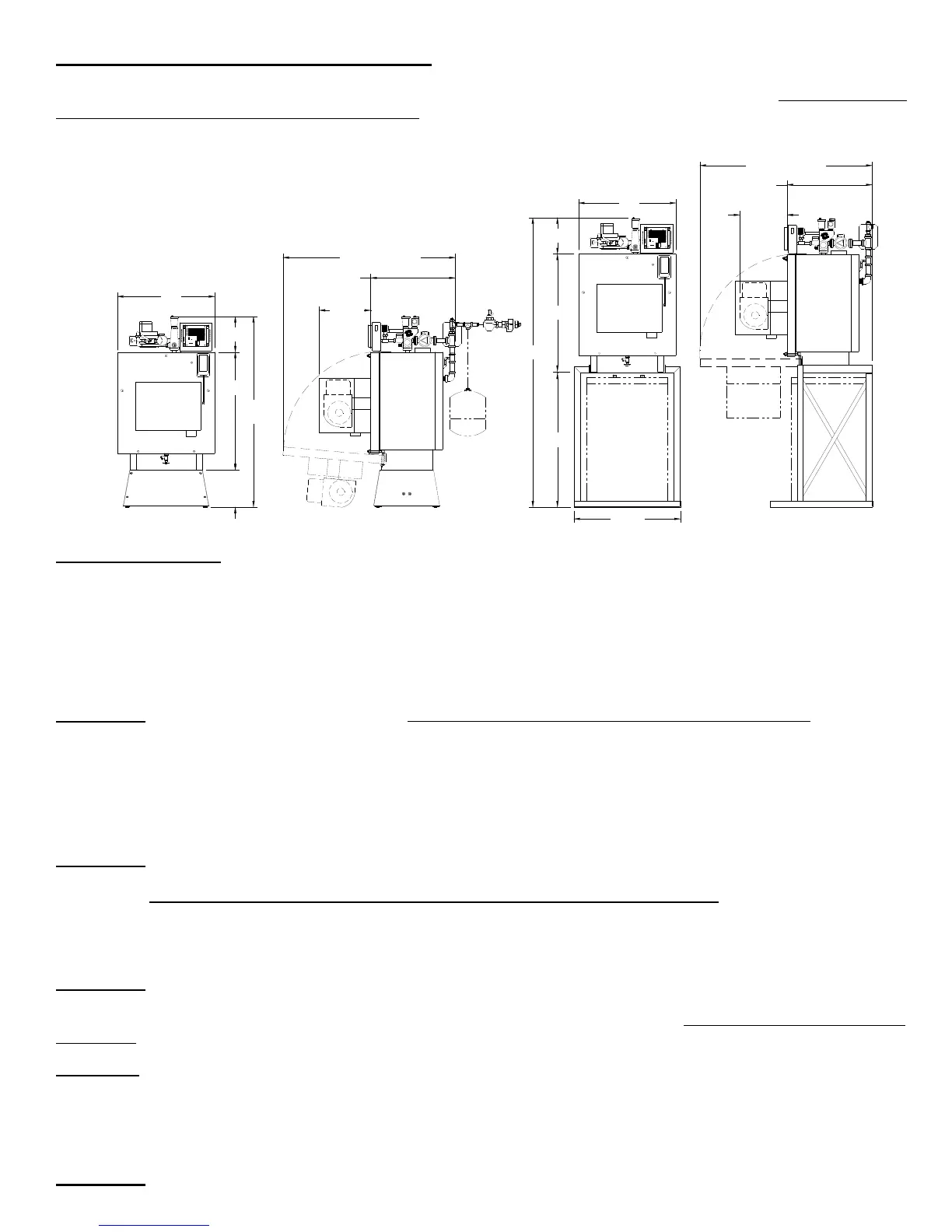
CLEARANCE for CLEANING and SERVICE
Installations should utilize one of Energy Kinetics boiler stands to provide a solid, level, and smooth foundation for the
boiler. NOTICE: Do not install on carpeting. Place the unit as near to the chimney or vent as possible allowing clearance
for front cleaning and service as shown in Figure 1B. If not using an Energy Kinetics supplied stand, provide a solid, level,
smooth, foundation with clearance for door opening and service. NOTICE: The stand must be level to allow for proper
venting of air from the boiler. The Frontier is manufactured with the BACK of the boiler higher than the front to assist in air
removal.
COMBUSTION AIR
The System 2000 Boiler must be installed in an area where adequate fresh air is available to support combustion. The
Frontier is provided with a sealed Air Box that can be piped to air outside the building. Piping of outside air directly to the
boiler is highly recommended because it completely isolates the boiler from the home environment, as well as greatly
reducing operating noise from the boiler.
Boiler with outside air piping: In modern houses with tight construction the connection of the Air Box to an outside air
source to provide combustion air is highly recommended. The outside air source must be located high enough above grade
to be at least 12” above expected snow accumulation.
WARNING: For systems with sidewall venting, combustion air piping from outside the building is required. The
Energy Kinetics sidewall vent kit contains specific instructions for installation that must be followed. Combustion air may be
supplied through PVC pipe. For EK-1 use, 2" pipe up to 20 feet in length with up to (5) 90-degree elbows. For EK-2 use, 3"
pipe up to 20 feet in length with up to (5) 90-degree elbows. A total equivalent length of 45 feet is allowed. Each 90-degree
elbow is the equivalent of 5 feet of straight pipe. For example, if three 90-degree elbows are used, then the length of pipe
run may increase to 35 feet. An unglued or Tek-screw joint allows the door to swing down when the air inlet pipe is
disconnected.
WARNING: Modern buildings of tight construction, as well as the operation of attic and exhaust fans, kitchen ventilation
systems, clothes dryers or fireplaces may create conditions of unsatisfactory combustion or venting. Provisions must be
made to use combustion air that communicates with a well-ventilated attic or with the outdoors (such as using a louver or
grate). The opening should have a free area of not less than one (1) square inch per 4,000 BTU per hour of the total input
rating.
Boiler without outside air piping:
WARNING: The confined space shall be provided with two permanent openings, one near the top of the enclosure and
one near the bottom. Each opening shall have a free area of not less than one square inch per 1,000 BTU per hour of the
total input rating of all appliances in the enclosure, freely communicating with interior areas having adequate infiltration from
the outside.
VENTING
When connecting the Gas Heat version of the Energy Kinetics SYSTEM 2000 boiler to gas vents or chimneys, all vent
installations shall be in accordance with Part 7, Venting of Equipment, of the National Fuel Gas Code, ANSI Z223.1/NFPA
54, or Section 7, Venting Systems and Air Supply for Appliances, of the CAN/CGA B149, Installation Codes, or applicable
provisions of the local Building Codes. Vent connectors serving appliances vented by natural draft shall not be connected
into any portion of mechanical draft systems operating under positive pressure.
WARNING: No solid fuel appliance or fireplace should be installed in a flue common with this heating appliance.
Fi
ure 1B
Boiler Clearance for Clearin
and Service
NOTE:
Tank Stand
Allows The Boiler
To Be Mounted
Over Top Of a 40
Gal Lo-Boy Tank.
NOTE:
All piping
(hydronic, gas &
inlet air) must
allow clearance
for door opening.
CAUTION
Lebanon, New Jersey
ERGY
ETICS
SYSTEM 2000
B
TEMP. SENS.
S
R
T4
T2
T1
THW
A2
A1
T3
EN
KIN
1
2
4
3
BURNER
CIRCULATOR
1
2
HOT WATE R
4
INDUCER
3
IND
B1
B2
CIRC
ZHW
Z1
Z4
24VAC
Z3
Z2
ENERGY MANAGER
CAUTION
Lebanon, New Jersey
ERGY
ETICS
SYSTEM 2000
B
TEMP. SENS.
S
R
T4
T2
T1
THW
A2
A1
T3
EN
KIN
1
2
4
3
BURNER
CIRCULATOR
1
2
HOT WATER
4
INDUCER
3
IND
B1
B2
CIRC
ZHW
Z1
Z4
24VAC
Z3
Z2
ENERGY MANAGER
24"
9"*
17"**
30"
9"
48"*
56"**
EK1: 41" / EK2: 49"
12-3/4"
EK1: 21-1/2"
EK2: 29-1/2"
29-1/4"
73"
30"
34"
24"
9"
EK1: 41" / EK2: 49"
11-5/8"
EK1: 21-1/2"
EK2: 29-1/2"
* Height of Frontier on a Low Profile Base
** Height of Frontier on a Standard Boiler Base

 Loading...