Frontier Gas Heat – PN 10-2027 – June 2018 12
8. Any improper operation of the common venting system should be corrected so the installation conforms with the
National Fuel Gas Code, ANSI Z223.1/NFPA 54 and/or CAN/CGA B149, Installation Codes. When resizing any
portion of the common venting system, the common venting system should be resized to approach the minimum size
as determined using the appropriate tables in Part 11 of the National Fuel Gas Code, ANSI Z223.1/NFPA 54 and/or
CAN/CGA B149, Installation Codes.
GAS BURNER MOUNTING
SYSTEM 2000 Boilers are shipped from the factory with the gas burner mounted. The burner flanges are designed to
insert the burner head 2-3/8” into the boiler. Energy Kinetics installs a ceramic sleeve, (the amulet), to protect the burner
head from the heat of combustion, and then seals the air tube flange joint with a high-grade retort cement.
NOTICE: Gas burners for field installation or for field replacement should be installed according to burner manufacturer
instructions, according to installation instructions below, and with consultation from Energy Kinetics for any special
considerations or adjustments.
Follow these instructions for field installation of Energy Kinetics supplied burners. Start by checking electrode and
flame sense rod position per manufacturer’s specifications prior to assembly to unit. Test fit the amulet by inserting the
amulet into the boiler opening. If the amulet doesn't easily slide into the boiler, then gently sand the outside diameter of the
amulet until it will fit into the boiler opening. Test fit the amulet onto the burner head. The amulet for the Carlin burners has
a smooth interior. If the amulet is a tight fit on the burner head, then slightly moisten inside the amulet with water.
Place a 3/8" bead of retort cement onto the burner head at the flange to air tube joint, and slide the (moistened) amulet
over the burner head and against the flange. Ensure proper seating of the amulet by pressing the amulet onto the burner
with a flat object. Leave the excess retort cement at the amulet to flange joint and the cement will provide an airtight seal of
the air tube flange to the boiler face.
The Carlin amulet does not have an edge and when fully seated the amulet will be flush with the front of the Carlin
burner head. If needed, trim the front edge of the amulet to be flush with the front of the burner head.
Once the amulet has been seated and trimmed, then install the burner into the boiler by carefully inserting the air tube
with amulet into the boiler opening while aligning the burner flange holes with the boiler studs. Install flat washers and nuts
onto the boiler studs and tighten all nuts evenly.
GAS BURNER SETTINGS
EK-1 Boilers are shipped from the factory preset for 120,000 Btu/Hr firing rate and EK-2 Boilers are shipped from the
factory preset for 200,000 Btu/Hr firing rate. The SYSTEM 2000 Boiler can be fired over a range of firing rates to suit the
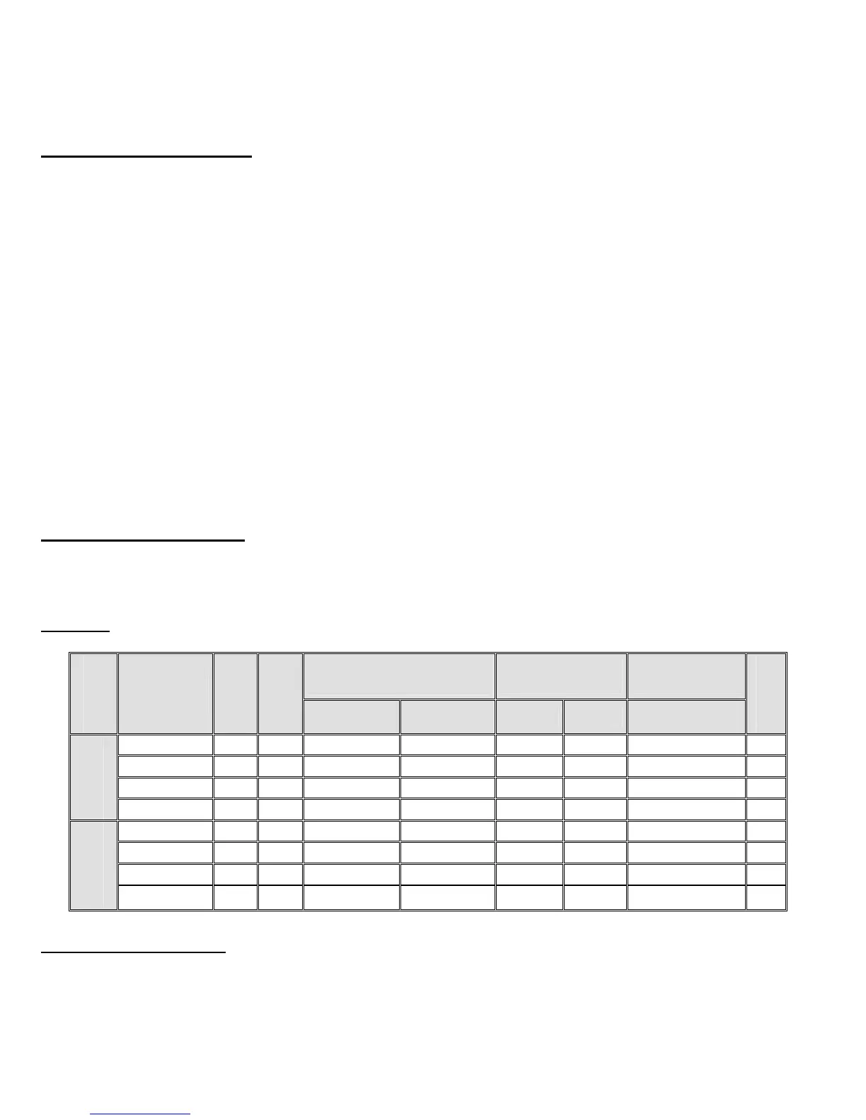
needs of the application. The following table lists approximate settings for Carlin EZ-Gas burners based on extensive
testing.
CAUTION: Final settings for each burner and firing rate for a particular installation must be determined by using
combustion test equipment and following the instructions given under "Start Up Procedure".
Model
Input
Btu/Hr
Chimney
Sidewall
Vent
Burner Orifice
Drill size
Approximate air
band setting
UTL - air tube
insertion length
Diffuser
Natural Gas LPG 1 Slot 2 Slot inches
EK-1
80,000 N Y #8 (0.199) #25 (0.149) 25 2-3/8” B
100,000 N Y #1 (0.228) #16 (0.177) 35 2-3/8” B
120,000
* Y Y C (0.242) #13 (0.189) 45 2-3/8" B
150,000 Y Y J (0.277) 7/32 (0.219) 60 2-3/8" B
EK-2
175,000 N Y N (0.302) C (0.0242) 40 2-3/8” A
200,000 * Y Y 21/64 (0.328) 17/64 (0.266) 50 2-3/8" A
225,000 Y Y T (0.358) 9/32 (0.281) 60 2-3/8" A
250,000 Y N X (0.397) 5/16 (0.312) 70 2-3/8" A
* Default Factory Setting
GAS PIPING SYSTEMS
The boiler and its individual shutoff valve must be disconnected from the gas supply piping system during any pressure
testing of the gas supply piping system at test pressures in excess of 1/2 psi (3.5 kPa, 14 in wc).
The boiler must be isolated from the gas supply piping system by closing its individual manual shutoff valve during any
pressure testing of the gas piping system at test pressures equal to or less than 1/2 psi (3.5 kPa, 14 in wc).
A manual shut off valve and a sediment trap must be provided in the gas piping upstream of the electric combination
gas valve at the boiler. The boiler and its gas connection must be tested for gas leakage before placing the boiler in
operation.

 Loading...