Frontier Gas Heat – PN 10-2027 – June 2018 16
ZONE PURGING:
Valves to isolate and purge individual zones should be installed according to good piping practices.
EXPANSION TANK SIZING: The type and size of expansion tank depends on the total system water volume. The
EK-1 Frontier contains 2-1/2 gallons of water and the EK-2 Frontier contains 4 gallons of water.
NOTICE: Sizing must
consider
cold start and hot operation due to system concepts of energy recovery and rapid heat up.
FILLING WITH WATER, VENTING, and PURGING
When piping is completed and all accessories installed the Converter and piping should be filled with water. The
Converter purges itself of air when properly installed.
NOTICE: AIR VENT CAP MUST REMAIN OPEN. Vent cap should
be removed and kept in a safe location. Each zone should be purged until a steady stream of water without air passes out
of purge hose. Vent all radiation.
NOTICE: DO NOT START BURNER UNTIL CONVERTER AND SYSTEM ARE FULL OF WATER. Fill to normal cold
system pressure, 10 to 12 psi on pressure gauge. Before placing system in operation, carefully check for leaks throughout
system. Tighten pipe joints, circulator flanges, check gaskets, etc., as needed.
BOILER WATER TREATMENT
Addition of boiler water treatment is recommended to reduce lime buildup inside the boiler. Energy Kinetics
recommends addition of one quart of 8-Way Boiler Treatment per 30 gallons system water. 8-Way Boiler Treatment is
recommended to treat water up to medium hardness. Call Energy Kinetics for more details about boiler water treatment
and about hard water conditions.
ANTI-FREEZE
Only non-toxic antifreeze (such as Propylene Glycol) should be used if adding anti-freeze to a System 2000 boiler.
Hard water should not be used in combination with generic antifreeze. Energy Kinetics supplies a quality inhibited
Propylene Glycol anti-freeze with orange dye and an antifoam agent. 8-Way Boiler Treatment can be added to Energy
Kinetics anti-freeze and is recommended in areas of medium water hardness.
NOTICE: Thoroughly clean system prior
to adding antifreeze.
TSP is recommended for removing flux and other oil based compounds. Once system has been
cleaned and flushed, then add antifreeze to obtain approximately a 30% by volume mixture of antifreeze in water. Call
Energy Kinetics for assistance in calculating how much anti-freeze to add to system.
WINTERIZING
NOTICE: If the SYSTEM 2000 Boiler may be exposed to freezing temperatures, such as a vacation home shut down
for the winter, then anti-freeze should be added to the boiler water. When a home is winterized by draining all domestic
water piping, then the SYSTEM 2000 Boiler must be protected. It is not recommended to drain the SYSTEM 2000 Boiler,
because introducing air into the boiler can cause rusting inside the boiler shell and also because the Energy Converter has
a spiral water passage that cannot be completely drained of water. When draining the domestic water piping system, be
sure to drain the domestic side of the plate heat exchanger. If the hydronic system will not be drained, then add enough
anti-freeze to protect the entire hydronic system including the boiler, piping, radiation, circulators, etc. If the hydronic
system will be drained, then add shut off valves to isolate the boiler and add anti-freeze to the boiler only, as follows. Drain
water from the boiler and then add anti-freeze to the boiler. Refill boiler with water and run boiler circulator through the
bypass to distribute antifreeze within boiler. Propylene Glycol in water will provide the following freeze protection: 30%
down to +8
o
F, 40% to -8
o
F, 50% to -27
o
F. Energy Kinetics recommends using 30% anti-freeze to obtain the best boiler
performance. Use over 30% anti-freeze only if lower temperature freeze protection is mandatory.
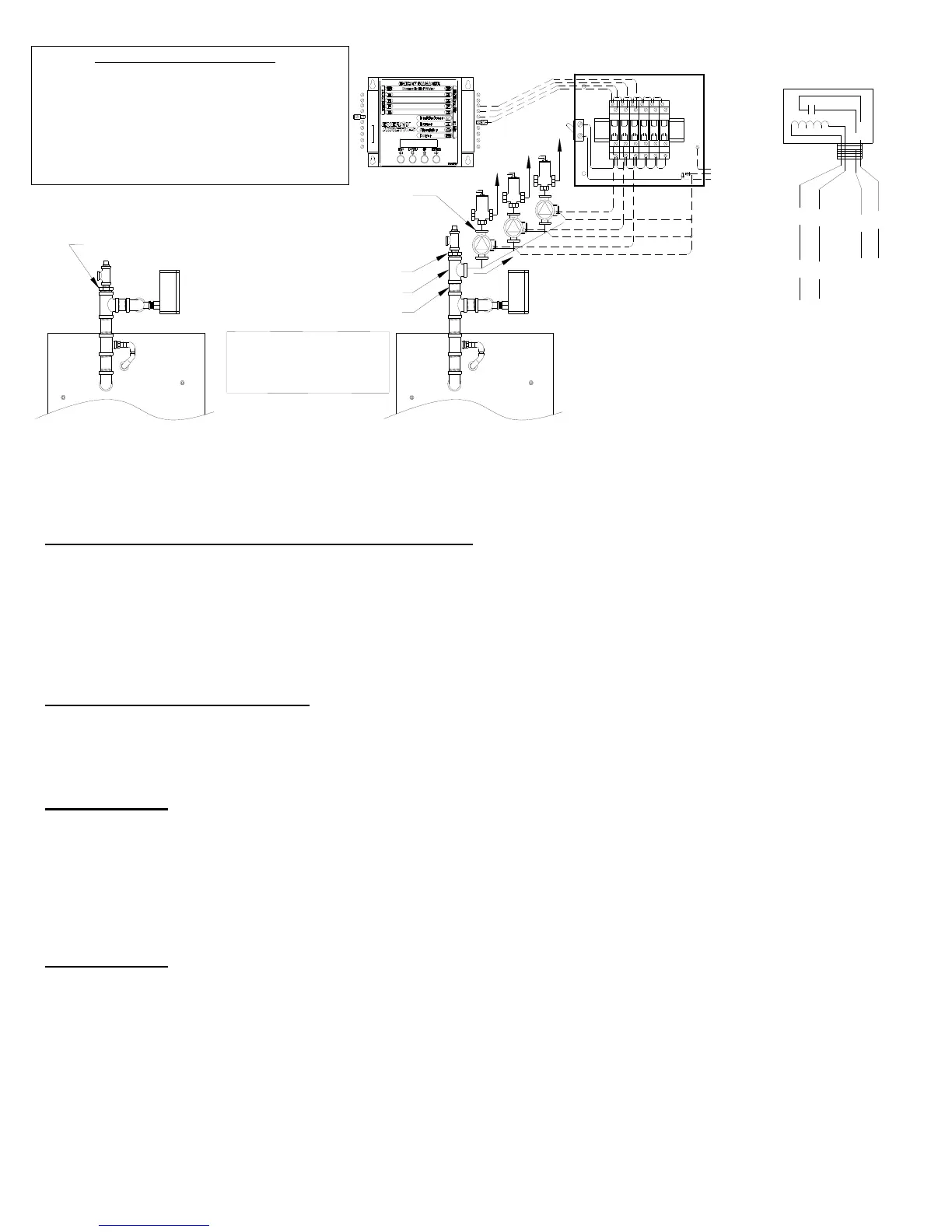
ORANGE
YELLOW
WHITE / YELLOW
WHITE/BLUE
EK# 10-0412-RIB (RIB# 2421C)
24V/120VAC Relay SPDT
24VAC
Coil Leads
To Manager,
Zx & 24V
N/O Contact
Leads
To CIRC,
Power To L1
Full Size Tee (added)
Nipple (added)
Bushing (moved)
1. Remove bushing installed at
factory from boiler supply.
2. Install a nipple (not supplied)
into the existing tee.
3. Install a tee (not supplies) on
to the new nipple.
4. Reinstall the bushing into the
new tee.
SUPPLY
Ground
Neutral
Line
120 VAC
Frontier Boiler Supply Piping
Modified piping for Zone
Circulators.
Looking from rear of boiler.
Circulators w/IFC or Circulators and Flow Checks
(Supply Side Preferred*)
*Circulator may be Installed Return Side
System Manager
5 Zone Circulator Relay Kit
P/N: 10-0412R-5 Shown
ZONE CIRCULATOR RELAY KITS
TO ACTIVATE EACH CIRCULATOR, USING The
SYSTEM MANAGER'S 24VAC OUTPUTS, USE ONE OF
ENERGY KINETICS MULTIPLE ZONE RELAY KITS.
5 ZONE RELAY KIT P/N: 10-0412R-5
10 ZONE RELAY KIT P/N: 10-0412R-10
15 ZONE RELAY KIT P/N: 10-0412R-15
OR INDIVIDUAL 24V RELAY(S) (EK#10-0412-RIB RIB
RELAY OR EQUIVALENT)
Bushing (Installed at Factory)
TEMP. SENS.
R
S
B
A2
A1
B2
CIRC
B1
24VAC
IND
T3
T1
T2
THW
T4
Z1
Z2
Z3
Z4
ZHW

 Loading...