Frontier Gas Heat – PN 10-2027 – June 2018 18
ELECTRICAL CONNECTION - LINE VOLTAGE
POWER SUPPLY: 120 VOLT 60 HZ, 7.5 Amperes
DANGER: Make All Connections With Power Off at Main Circuit Box
Caution: Label all wires prior to disconnection when servicing controls. Wiring errors can cause improper and
dangerous operation.
System 2000 requires 120 VAC. The supply voltage must be within 108 VAC min / 132 VAC max for reliable operation
of the boiler and the Manager. An easy way to check the supply voltage is to plug a voltmeter in at the service outlet
located on the side of the system junction box.
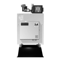
Figures 3A and 3B: Connect power from a separate 15 AMP fused circuit. Pigtails are provided for the line voltage
power connection. Connect black pigtail to hot, white pigtail to neutral, and the green pigtail to ground. The system switch
is included so power can be shut off at the unit for servicing. The boiler must be electrically bonded to ground in accordance
with the requirements of the authority having jurisdiction or, in the absence of such requirements, with the National
Electrical Code, ANSI/NFPA 70 and/or the Canadian Electrical Code Part I, CSA C22.1, Electrical Code.
WARNING: The junction box is wired at the factory with the service outlet always powered, even with the System
Emergency Switch turned off. To have the service outlet controlled by the System Emergency Switch, move the service
outlet black lead to top lug of system switch.
LOW VOLTAGE WIRING
DIGITAL MANAGER OPERATES ONLY ON 24 VOLT 60 HZ POWER
WARNING: Make All Connections With Power Off at Main Circuit Box
A typical low voltage wiring diagram for the Digital Manager is shown in Figure 4A. Thermostats must be located on
inside walls away from cold drafts, windows or heat from fireplaces, appliances or sunlight. Set thermostat heat anticipators
to 0.1 amps (or "gas" if gas/electric option). Call Energy Kinetics to request alternate low voltage wiring diagrams to handle
special situations such as air handler wiring, heat pump wiring, isolation relays for thermostats, and isolation relays for heat
motors or circulators, etc.
The single 24-volt/50VA transformer is suitable for the Digital Manager and five zone outputs (zone valves or relays).
NOTICE: Additional load such as extra valves may require greater transformer capacity. To add transformers, wire in
parallel as follows: wire terminal “A” on one transformer to “A” on the other. Repeat with other
low voltage terminal “B”. Be sure to verify 24VAC output from all transformers.
The Digital Manager is designed for up to five heating zones. Use Energy Kinetics supplied zone valves with two wire
connections. For more than five heating zones, use Energy Kinetics expanded 10 or 15 zone Digital Manager, or call
Energy Kinetics for alternatives.
Figure 4A
 Loading...


