Frontier Gas Heat – PN 10-2027 – June 2018 19
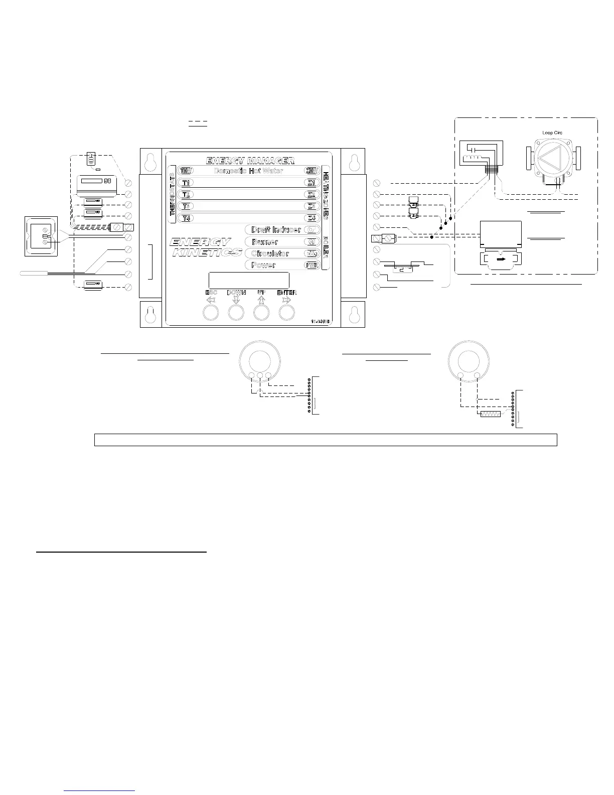
LOW VOLTAGE WIRING DIAGRAM
INSTALL ENERGY MANAGER
The Energy Manager is shipped in its own protective shipping box. NOTICE: The option switches can be set very
easily before the Manager is installed. Locate the pre-wired quick connectors fastened to the front of the junction box by
two cable ties. Cut the two cable ties and discard. Fasten the Energy Manager to the junction box with the four corner
screws. Slide the two quick connectors onto the Energy Manager. Label each zone on the manager, using the adhesive
labels supplied.
TEMP. SENS.
RED
WHITE
R
S
BLACK
B
A2
A1
B2
CIRC
B1
MAIN CIRC RELAY
24VAC
IND
ZONE 2
ZONE 1
HOT WATER TANK
ZONE 1
ZONE 2
ZONE 4
LOAD
A
B
Thermistor or
Digital Sensor
(Located in Boiler
Return Piping)
T3
T1
T2
THW
T4
Z1
Z2
Z3
Z4
ZHW
HOT WATER CIRC RELAY
ZONE 3
or ADDITIONAL ZONE
ZONE 3
ZONE 4
Transformer
24VAC 50VA
T2
T4
A2
S
TEMP. SENS.
R
B
A1
T3
THW
T1
Tx*
CR
W
T2
T4
A2
S
TEMP. SENS.
R
B
A1
T3
THW
T1
Tx*
Resistor between
A2 and Tx
POWER STEALING OR WIFI THERMOSTATS THAT
REQUIRE A COMMON
CONNECT THE COMMON OR C TERMINAL ON THE
THERMOSTAT TO THE A2 TERMINAL ON THE
MANAGER
*Tx CAN BE T1, T2, T3, T4 OR EVEN THW IF USED AS A
HEATING ZONE
POWER STEALING THERMOSTAT
USING 2 WIRES
USING 15 WATT 200 OHM RESISTOR
(OR ISOLATE FROM MANAGER WITH A RELAY)
*Tx CAN BE T1, T2, T3, T4 OR EVEN THW IF
USED AS A HEATING ZONE
R
W
FIELD WIRING
FACTORY WIRING
*Field Wiring terminated to input terminal A1 and to output terminal 24VAC are to
be wired into the open lugs provided at those locations.
NOTE: ALL ENERGY DISPLAY MANAGERS (W/LCD DISPLAY} ARE DESIGNED TO WORK WITH NEST THERMOSTATS WIRED DIRECT USING ONLY 2 WIRES
Injection Zone
Valve
ZONE 3
Loop Circ Relay
Connected to Z11
ZONE 4
N
L1
WHEN SECONDARY ZONES ARE ENABLED
(PRIMARY/SECONDARY PIPING)
ZONE 3 BECOME THE INJECTION ZONE
ZONE 4 BECOMES THE LOOP CIRC
STACK LIMIT
T
T
TO BURNER
RELAY
 Loading...


