Frontier Gas Heat – PN 10-2027 – June 2018 15
PIPING
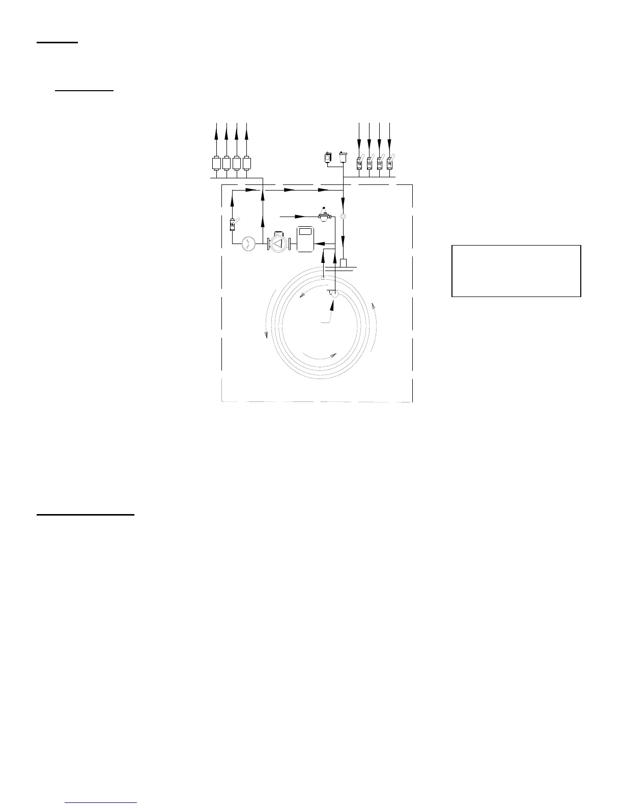
All piping and accessory connections should follow good practice using approved joint sealants. Figure 2C indicates a
general system piping arrangement and options.
Piping of individual systems may vary from Figures. Supply and return
connections are 1”NPT on the EK1 and 1-1/4”NPT on the EK2.
WARNING: A low water cut-off must be field installed if the boiler is installed above radiation level or if required by the
authority having jurisdiction. A low water cut-off is available from Energy Kinetics as an option.
Figure 2C
indicates a typical flow schematic for boiler water feeding multiple zones.
Call Energy Kinetics to obtain piping and wiring instructions for alternate applications, such as hydronic heating, radiant
heating, domestic hot water, swimming pool heating, multiple boilers, injection loops, etc.
Figures 2A and 2B indicate general system piping arrangement and options.
Piping of individual systems may vary from
Figures.
ZONE CONTROL
ZONE CONTROL BY VALVE: The SYSTEM 2000 Boiler is designed to provide multi-zone control of the heating
system. Energy Kinetics recommends and supplies two wire, full port, 24-volt zone valves for control of each heating zone.
A system with a single heating zone still requires a zone valve to provide control for preheat of unit and to maintain
minimum temperature during operation.
ZONE CONTROL BY CIRCULATOR: Zone control by circulators requires a flow valve, circulator and 24-volt relay (fan
type such as Honeywell R8225B) for each zone. The main circulator, domestic heat exchanger and bypass line are still
used in these cases.
NOTICE: An additional tee must be installed into the supply on the inlet side of the main circulator.
This tee is the supply for circulators with returns for these zones into normal return location.
Use Energy Kinetics
Smart Thread Sealant
P/N 10-0620
Figure 2C
Supply
Return
Return
Supply
Boiler Feed
Energy Converter
Typical Flow
Schematic
Factory piping shown within dashed line
Supply
Boiler Bypass
Digital
Sensor
 Loading...


