Frontier Gas Heat – PN 10-2027 – June 2018 14
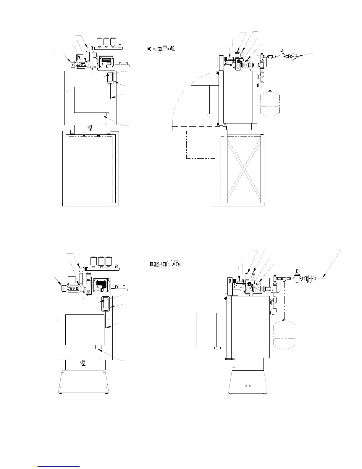
BOILER MOUNTING on STANDARD BASE, Figure 2B: The back support bar should be mounted to the holes just in
front of the 2” slot. Line up the rear holes in the legs with the holes in the back support bar. Two sets of 5/16” x 1-1/2”
bolting hardware are provided and are used to secure the boiler to the back support bar.
PIPING SO THE DOOR CAN OPEN: To avoid conflicts with the door opening, piping should be in accordance with
Figures 2A, 2B or dimension D in Figure 1B. The door opens and drops into the notches on the boiler legs. The burner
and air box also need clearance when the door opens. Do not locate any piping in front of the tank unless clearance from
the door is verified. This also applies to the gas line piping and the combustion air piping. NOTICE: Air inlet pipe must be
disconnected to allow door to swing down.
Figure 2B
Figure 2A
NOTE:
Tank Stand
Allows The Boiler
To Be Mounted
Over Top Of a 40
Gal Lo-Boy Tank.
Combustion
Air Inlet
NOTE:
All piping must
allow clearance
for door opening.
24 VAC C O N N E CTI O N ON LY.
CAUTION
Lebanon, New Jersey
ERGY
READ INS T RU CT I O NS BEFORE
MAKING ANY CONNECTIONS
ETICS
SYSTEM 2000
B
TEMP. SENS.
S
R
T4
T2
T1
THW
A2
A1
T3
EN
KIN
1
2
THERMOSTAT
4
3
BURNER
190
160
150
170
POWER
CIRCULATOR
130
140
1
2
HOT WATER
HEATING
4
ONLY
CHIMNEYLESS
INDUCER
3
IND
B1
B2
CIRC
ZHW
Z1
Z4
24VAC
Z3
Z2
100
ALARM
120
ENERGY MANAGER
Zone Valves
Expansion Tank to
be located in return
piping or at the inlet
side of the pump.
Supply
3/4" Air Vent
Bypass
Return
Relief Valve
System Circ
Puff Switch
Flue Box Test Port
Combustion/Over fire
Test Port
High Limit
Main/System Circ
Supply
T&P Gauge
Feedwater
Connection
Premier Option: Combo
Auto Feed/Backflow
Preventer
Premier Option: Return
Ball & Ball Purge Valves
CAUTION
Lebanon, New Jersey
ERGY
ETICS
SYSTEM 2000
B
TEMP. SENS.
S
R
T4
T2
T1
THW
A2
A1
T3
EN
KIN
1
2
4
3
BURNER
CIRCULATOR
1
2
HOT WATER
4
INDUCER
3
IND
B1
B2
CIRC
ZHW
Z1
Z4
24VAC
Z3
Z2
ENERGY MANAGER
High Limit
Main/System Circ
T&P Gauge
Supply
Zone Valves
Premier Option: Return
Ball Valve & Purge
Feedwater
Connection
Premier Option: Combo
Auto Feed/Backflow
Preventer
Expansion Tank to
be located in retur
piping or at the inle
side of the pump.
Combustion
Air Inlet
Combustion/Over fire
Test Port
Puff Switch
Flue Box Test Port
Supply
3/4" Air Vent
Bypass
Return
Relief Valve
System Circ
 Loading...


