Frontier Gas Heat – PN 10-2027 – January 2016 33
ANNUAL TUNE UP & INSPECTION
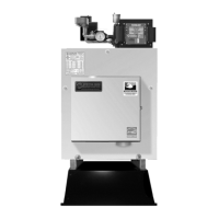
Step 1 Initial Test (Draft Loss & CO
2
)
Air box cover must be in place before testing
1. Remove 1/8” brass plug from the “over fire” test port (2) next to
the burner and the flue box (1) next to the puff switch. Check
draft through the “over fire” test port (2) and at the flue box (1).
Use a 12” long piece of ¼” O.D. steel or copper tubing and
insert it approximately 8” into the boiler. Connect this tube to
your test probe using a piece of hose.
Clean boiler flue passage if the draft difference between the flue
box (1) and “over fire” test port (2) is greater than 0.04” w.c.
2. Check CO
2
through the over fire test port (2). Insert the 12”
long steel or copper tube approximately 8” in through the test
port. Natural: CO
2
: 8.6%-9.2%, O
2
: 5.5%-4.5%
LPG: CO
2
: 9.7%-10.7%, O
2
: 6.0%-4.5%
Step 4 Clean Boiler
Do Not Touch, Vacuum or Remove Chamber!
Note: If there is evidence of condensing in last pass:
1. Check for cold returns.
2. Open by-pass valve fully.
3. Verify Digital Manager Option Switch 1 to “ON”.
4. If condensing persists, increase firing rate.
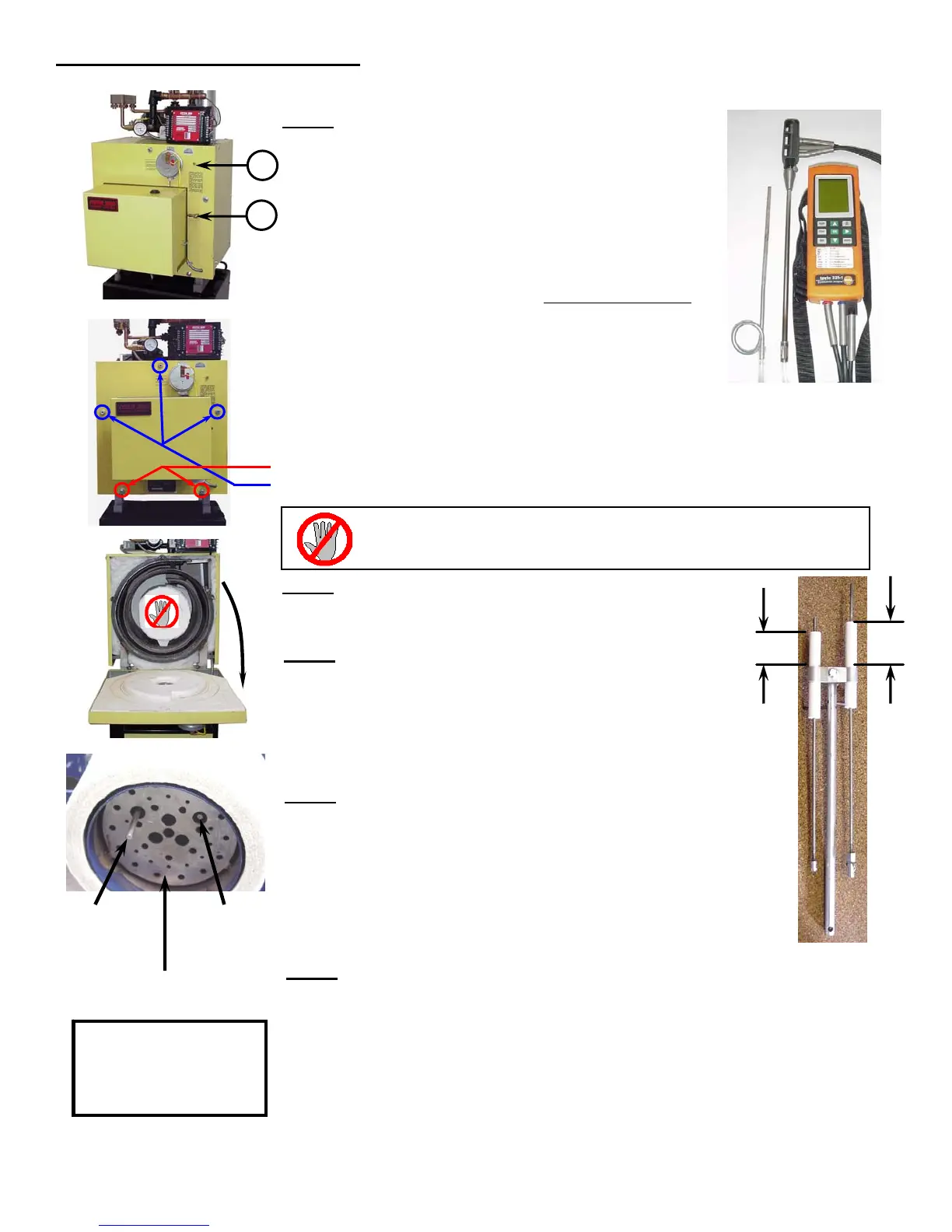
Step 5 Remove Drawer Assembly
(Refer to burner manual for detailed instructions on removal and for burners
other than EZ-Gas)
1. Close the front cover and finger tighten a nut on the top center stud to
hold the cover closed while working on the burner. Do not tighten the rest
of the nuts at this time because you will need to open the cover up again
to check the drawer assembly to the diffuser plate
2. Check porcelain condition.
3. Check and clean flame sense rod.
Step 6 Check Burner
(Refer to burner manual for complete details and for burners other than EZ-Gas)
1. Check Fan/Air Inlet for dirt or lint.
2. Install drawer assembly carefully lining up the ignitor electrode and flame sense
rod. Open the front cover and check, neither should be any closer to the diffuser
plate than 1/16”. Adjust if necessary.
3. Check amulet for cracking or other physical damage. Replace if necessary.
(See amulet replacement section in installation manual).
4. Check burner diffuser plate.
Note: All burners
require “Amulet”
retention head
protector.
1
2
Step 3 Inspect Flue Passage
If passage is clean, no scale, then proceed to step 5.
Clean ONLY if dirty.
Step 2 Open Front Cover
Turn off power to system and close main manual gas valve when servicing.
1. Loosen, but DO NOT REMOVE (2) lower nylock nuts on hinge bolts.
2. Remove (3) upper nuts and support cover while opening.
DO NOT remove or touch combustion chamber for
inspection or when cleaning boiler!
Please refer to installation manual and burner manual for complete details and for burners other than EZ-Gas.
Electronic Analyzer
Drawer Assembly
Diffuser Plate
Flame Sense Rod
Tip should extend
in front of diffuser
by 1-1/4”.
Ignitor Electrode
Tip should be
flush with inside
surface of diffuser.
1 3/8”
1 3/4”
 Loading...


