Do you have a question about the EnerSys alpha Matrix C16 and is the answer not in the manual?
Covers warnings to prevent injury or death from various hazards.
Provides information to prevent damage or complete tasks.
Highlights specific regulatory or code requirements.
Explains image usage and company liability limitations.
Lists phone numbers and website for support inquiries.
Defines the scope and relevance of the manual.
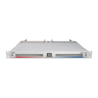
Explains the unit's functionality and key capabilities.
Details the process for unpacking and checking the product.
Covers ambient temperature, air flow, and mounting safety.
Addresses circuit loading, earthing, and disconnect device needs.
Instructions for attaching the unit to rack rails.
Steps for securing cables at the rear of the unit.
Details the installation of the optional rear rack support.
Provides specifications for chassis ground connections.
Step-by-step guide for establishing the ground connection.
How to connect input power using straight lugs.
How to connect input power using 90-degree lugs.
Attaching shields to straight input bus bars.
Attaching shields to 90-degree input bus bars.
Steps for attaching customer-provided output cables.
Details connecting Form-C dry alarm contacts for monitoring.
Procedure for inserting breakers into the panel.
Steps to connect the network cable for remote monitoring.
Explains how to interact with the SmartSwitch display.
Describes the data and status shown on the home screen.
Steps to identify and record installed breakers.
Procedure to configure each breaker's current rating.
Accessing detailed load and alarm information per circuit.
Setting input bus rating for overcurrent protection.
Setting thresholds for breaker overcurrent warnings.
Adjusting displayed bus voltages for accuracy.
Managing panel defaults, demo mode, and system information.
Configuring network settings for web-based monitoring.
Describes how to move through the web server pages.
Covers network, notification, email/SNMP, site, channel settings, and firmware upload.
Explains how to navigate menus using the SmartSwitch.
Provides a visual map of the SmartSwitch menu hierarchy.
Details the layout and function of the logic board components.
Steps to inventory installed breakers using LEDs.
How to silence, disable, or re-enable the alarm beeper.
Steps to perform a full factory reset.
Step-by-step guide for removing a circuit breaker.
Steps for safely removing output connectors.
Details electrical, mechanical, and environmental specs.
Lists UL file number and standard.
Lists available Matrix C16 panel models and part numbers.
Lists compatible accessories, replacement parts, and circuit breakers.
Details AWG, length, color, and part numbers for cables.
Provides dimensional drawings for the single-input model without safety shields.
Shows dimensions for single-input model with safety shields.
Provides dimensional drawings for the dual-input model without shields.
Shows dimensions for dual-input model with safety shields.
Provides company address, phone, website, and copyright notice.
| Brand | EnerSys |
|---|---|
| Model | alpha Matrix C16 |
| Category | Power distribution unit |
| Language | English |