10
C048-725-30 Rev. B (01/2020)
4.3 4.3 Ground InstallationGround Installation
DO NOT ENERGIZE THE PANEL BEFORE CHASSIS
GROUND IS CONNECTED�
CAUTION!
The chassis ground is located on each side of the panel� A two
hole lug landing position is provided per side� See table below
for termination information. A minimum of #6 AWG chassis
ground cable is required�
IMPORTANT: Grounding hardware not included� A properly-
sized grounding conductor must be installed per NEC
(250�122)�
Table 2. Ground Termination Summary
TWO HOLE
LANDING
TYPE
HOLE/
STUD SIZE
CENTER
TO
CENTER
RECOMMENDED
TORQUE VALUE
Threaded Insert 1/4in-20 5/8in 90in-lbs
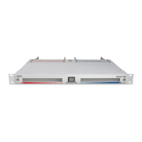
Step 1. Connect the lug to the chassis (see Figure 8) with the
included 1/4in-20 hardware� Make sure heat shrink and
no-oxide compound are applied appropriately prior to
attachment�
Step 2. Torque the fasteners to 90in-lbs�
Figure 8. Chassis Ground Connection