11
C048-725-30 Rev. B (01/2020)
4.4 4.4 Input ConnectionsInput Connections
WARNING! ELECTRICAL HAZARD
TO PROTECT PERSONNEL AND EQUIPMENT,
ENSURE ALL INPUT POWER FEEDS ARE NOT
ENERGIZED BEFORE INSTALLING THEM�
ELECTRICAL INSTALLATION SHOULD ONLY BE
PERFORMED BY QUALIFIED PERSONNEL WITH
PROPER TOOLS AND PROTECTIVE SAFETY
EQUIPMENT�
MAKE SURE THAT ALL FEEDER CABLES HAVE
HEAT SHRINK APPLIED PRIOR TO TERMINATION,
AND THAT NO-OXIDE COMPOUND IS APPLIED
TO ALL COPPER-TO-COPPER CONNECTIONS�
USE ONLY COMPONENTS AND CRIMPING TOOLS
APPROVED BY AGENCIES OR CERTIFYING
BODIES RECOGNIZED IN YOUR COUNTRY OR
REGION�
NOTICE:
Table 3. Electrical Termination Summary
TWO HOLE
LANDING
TYPE
HOLE/
STUD SIZE
CENTER
TO
CENTER
RECOMMENDED
TORQUE VALUE
Through Hole 3/8in 5/8in - 1in 145in-lbs
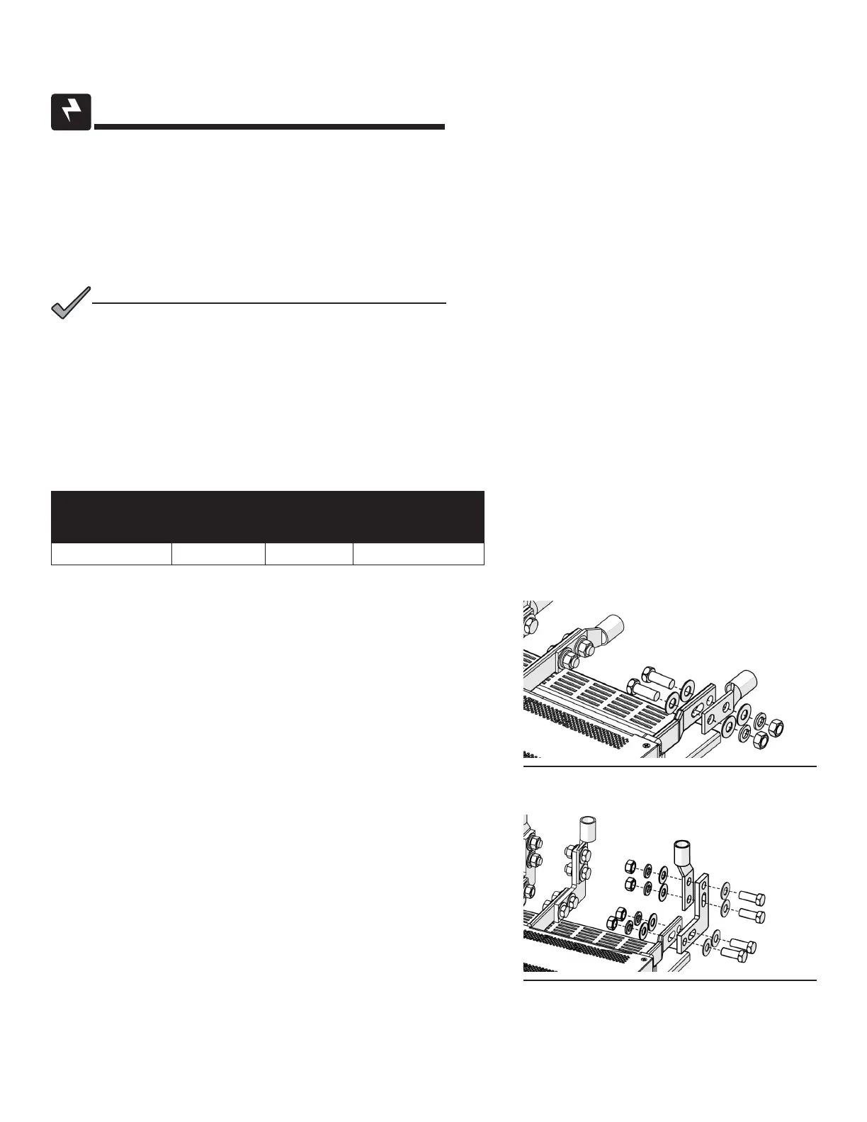
4.4.1 4.4.1 Straight Lug Input CongurationStraight Lug Input Conguration
(See Figure 9)
Step 1. Secure the HOT input cables lug(s) to the HOT input bus
bar(s) with the included 3/8”-16 x 1” hardware� Torque
the bolts to 145 in-lbs�
Step 2. Secure the RTN cable lug(s) to the RTN input bus bar(s)
with the included 3/8”-16 x 1” hardware� Torque the bolts
to 145 in-lbs�
4.4.2 4.4.2 Optional 90 Degree Lug Input CongurationOptional 90 Degree Lug Input Conguration
(See Figure 10)
Step 1. Secure the 90 degree HOT input bus bar adaptor(s) to
the HOT input bus bar(s) with the included 3/8”-16 x 1”
hardware� Torque the bolts to 145 in-lbs�
Step 2. Secure the 90 degree RTN input bus bar adaptor(s) to
the RTN input bus bar(s) with the included 3/8”-16 x 1”
hardware� Torque the bolts to 145 in-lbs�
Figure 9. Straight Input Lug Installation
Figure 10. 90 Degree Input Lug Installation