XF Rev: 7, 2008-10-14 Page 14
6 THRUSTER INSTALLATION
WARNING:
• Do not install the thrusters in areas where inflammable or explosive
gases may be present.
• Thruster installation must only be carried on by qualified personel.
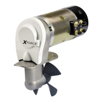
A: Pull-in tools;
Spacer/nut, washer and M8 nut.
B: Bracket mounting bolt set;
Bolts, washers and locknuts.
C: Propeller mounting set;
Driving pin, washer and locknut.
These instructions assume a tunnel has been correctly mounted in the hull.
6.1 Preparations
Start work from the inside. Remove all possible remains from the moulding
process and hone down with a file.
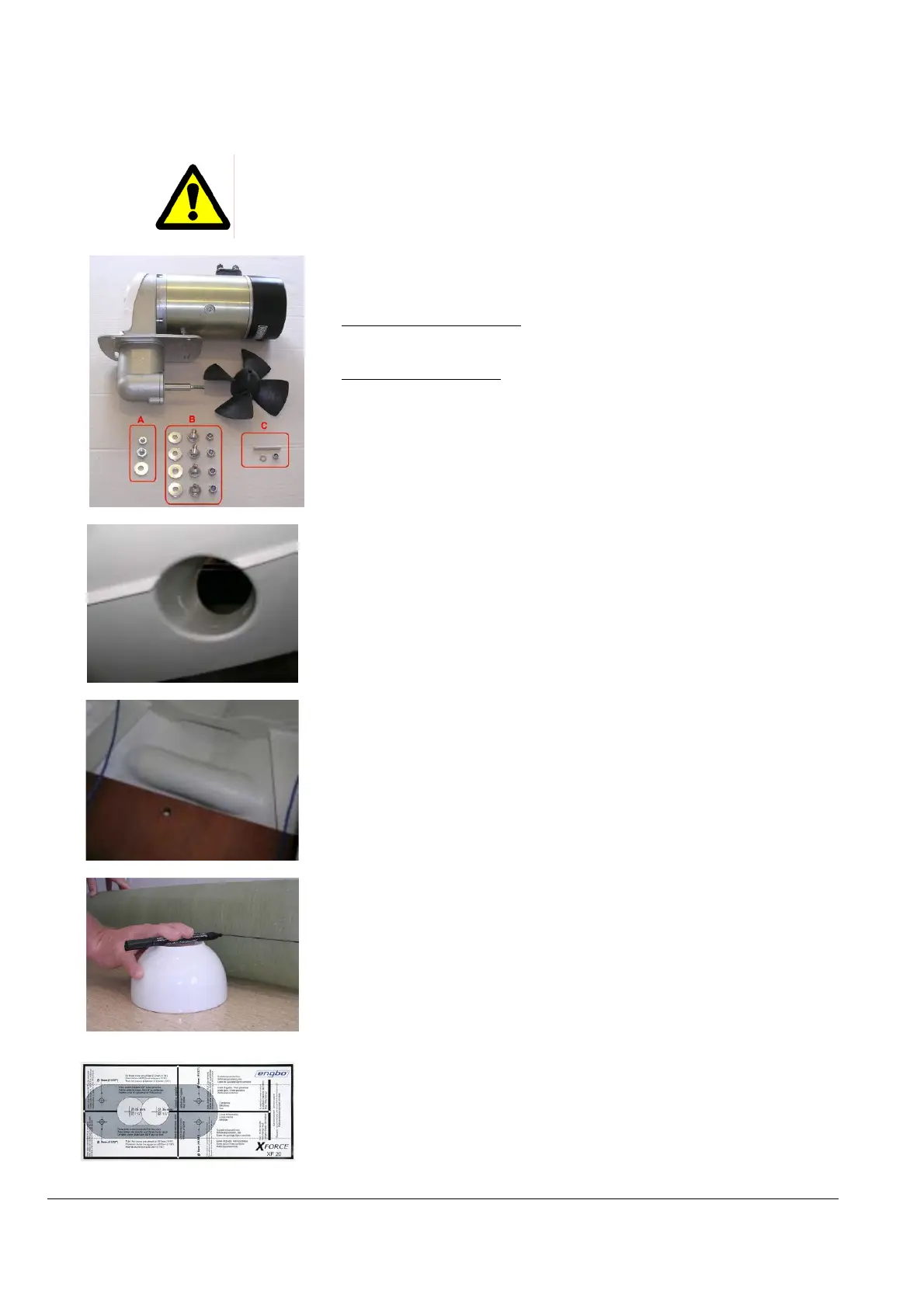
6.1.1 Determine the centre lines
Define a tunnel centre line and the optimum propeller centre line.
The tunnel centre line is determined with reference to the tunnel and not to
the boat.
NB: See left hand picture for suggestion on how to find a centre line or line up
the template sticker spectly on the tube.
6.1.2 Installation template
The darkest grey area shown on the installation template is the contact area
for the bracket and must not be removed. Before installing the bracket,
remove the sticker, clean and dry the contact area to achieve optimal contact.
 Loading...