XF Rev: 7, 2008-10-14 Page 15
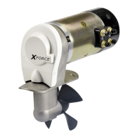
Fasten the installation template sticker exactly over the centre line and cross
line.
(The propeller may be mounted slightly offset)
The bow thruster may be mounted at any angle, from 0° - 90°. Installation
from 45° to horizontal requires a support for the motor.
WARNING: The motor has to be properly supported to offload weight and
tension on tunnel / transom.
6.1.3 Pre-drill
All marked holes must be pre-drilled Ø 2.0 mm (1/16”)
Use a centre punch prior to drilling.
6.1.4 Drilling holes for the bracket bolts
The 4 bracket holes must be drilled Ø 9 mm (11/32”)
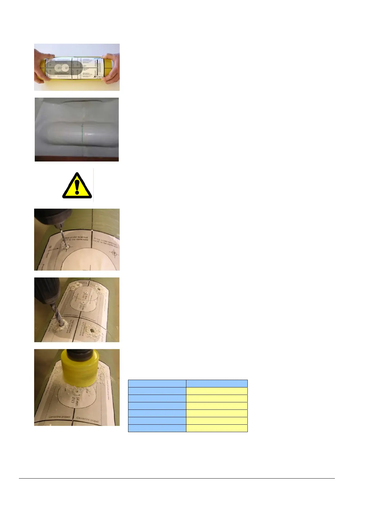
6.1.5 Drilling the insertion hole
Use a saw drill designed for glass fibre cutting, with the correct size according
to the thruster model to be fitted. Slow speed is recommended.
Thruster model Saw drill (Ø)
XForce 20
Ø 35 mm (1 ⅜”)
XForce 40
Ø 54 mm (2 ⅛”)
XForce 60
Ø 54 mm (2 ⅛”)
XForce 75
Ø 67 mm (2 ⅝”)
XForce 90
Ø 67 mm (2 ⅝”)
XForce 130
Ø 83 mm (3 ¼”)
 Loading...