10
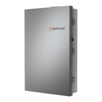
IQ System Controller 3 INT Quick Install Guide
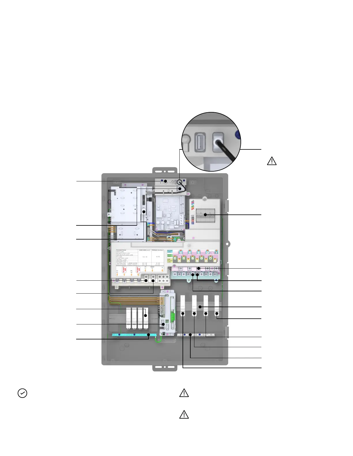
Backup load lugs
Manual
override
Ethernet port
IQ Gateway LED status
and buttons explained
on door label and in
Operation section of
this document
IQ System Controller
LED status explained
in the label on the
dead front
IQ Gateway USB connection
Connect at the time
of installation
Non-backup load lugs
Mains lugs
Backup loads breaker
Mains breaker
Non-backup loads breaker
Neutral terminals
Ground terminals
PV lugs
IQ Battery lugs
DER breakers
System shutdown
terminal
Once the dead front is removed the IQ System Controller 3 INT
looks like the diagram below.
DIN rails are provided to install breakers. Use conductors (line,
neutral, and ground) and breakers of proper ampacity and
protection requirements according to local codes.
Before connecting the wires, refer to the wiring table, torque
recommendations, and local codes for any specic local
requirements.
Internal view of
IQ System Controller 3 INT
IQ Gateway breaker
(pre-installed and pre-wired)
DIN rails
NOTE: Breakers for IQ Battery, mains, and non-backup/
backup loads are not supplied with IQ System Controller 3 INT
and must be purchased separately.
In Australia and New Zealand, the neutral will not be switched.
Section B - Wiring
Ensure to connect the USB cable from controller PCBA to
IQ Gateway before closing the dead front.
Ensure that wires are not pinched while re-attaching the dead
front.