31
IQ System Controller 3 INT Quick Install Guide
Connecting cellular modem
NOTE: The cellular connection is only intended as a backup.
Primary internet connectivity must be provided using the
homeowner’s Ethernet/Wi-Fi. Cellular connectivity is subject
to network operator coverage and signal strength.
The IQ System Controller 3 INT is packaged with the Mobile Connect
Cellular modem - CELLMODEM-M1-06-AT-05.
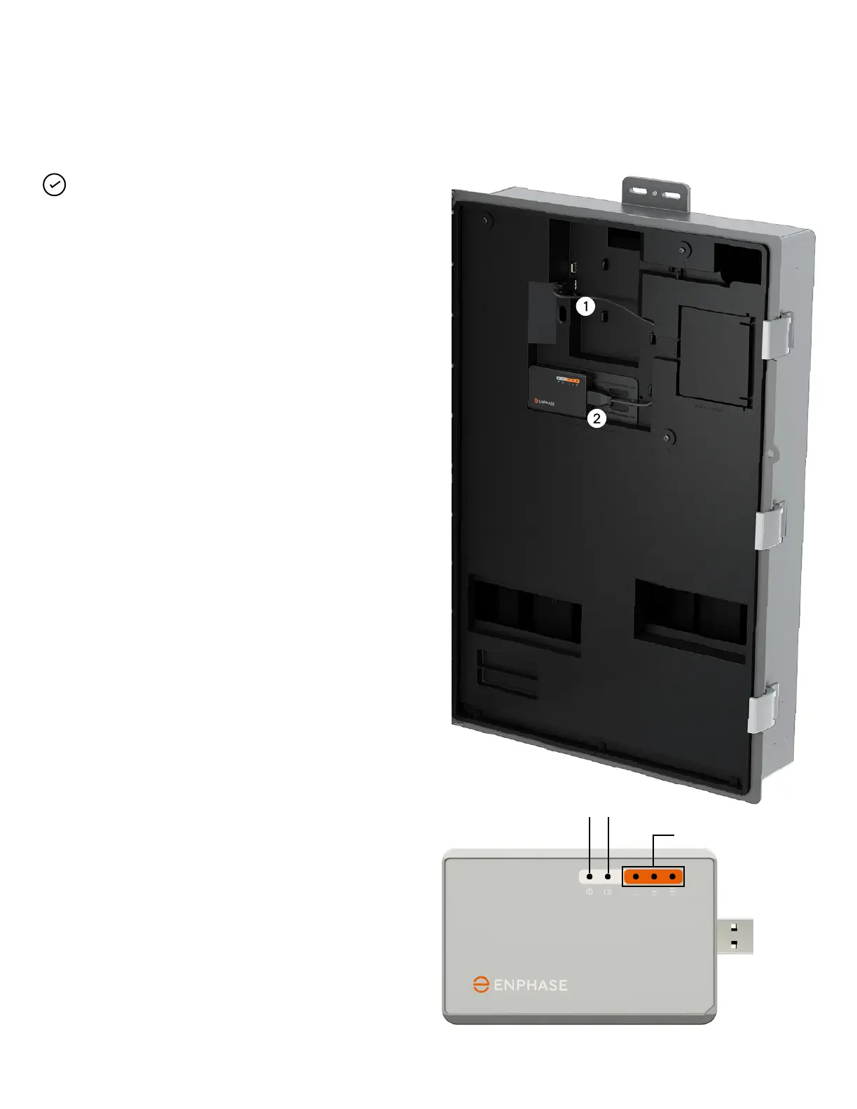
Connecting the USB cable
1. Connect the USB cable to the USB port(s) on the
IQ System Controller.
2. Connect the cable to the USB port of Cellular modem.
Checking the Cellular modem status LEDs
The modem has the following status LEDs
• Power
• Link
• Signal
The LEDs are located on the upper right side of the front panel, as
shown in the below diagram:
The Power LED turns green when the modem is powered. After a
few minutes, the Link status LED on the Cellular modem ashes
to indicate a network connection. The Signal LEDs indicate signal
strength as shown in the table on the next page.
No additional conguration is needed.
Power LED Link LED
Signal LEDs