29
IQ System Controller 3 INT Quick Install Guide
PV shedding
PV shedding allows oversized PV systems with IQ7 and S series
microinverters to be installed with grid forming batteries and
IQ System Controller 3 INT.
PV microinverters operate normally when the system is on-grid.
When the system goes o-grid the auxiliary contacts disconnect
the PV circuit, to avoid overloading the IQ Battery 5P.
NOTE: PV shedding is required when the total continuous
power (kVA) from PV on a phase exceeds the 150% of
continuous power (kVA) from the batteries on that phase.
In such scenarios PV shedding can be used to shed PV
microinverter circuits to reduce the PV continuous power
when the system is o grid.
Section B - Wiring
AUX wiring:
PV shedding/load control
Load control
In o-grid state low-priority loads with high power requirements
may deplete energy storage. Auxiliary contacts can be used to shed
these large loads to help maintain energy in the storage system.
Contactor selection
• A 25 A contactor is required for PV circuit shedding.
• Contactors used for load shedding need to be sized in
accordance with load rating.
• A Normally Open (NO) type contactor must be used in both
cases.
• For PV shedding an AC-7a or AC-7b rated contactor can be
used.
• For load control 230 V 50 Hz rated contactors which conform
with the IEC EN 61095 utilization categories must be used.
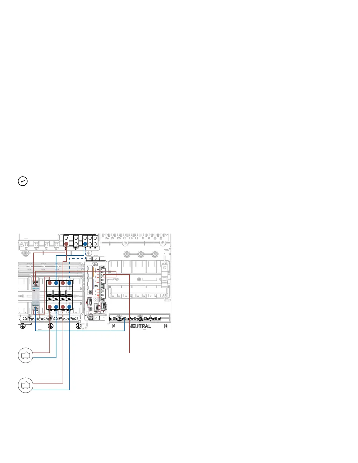
Wiring for PV shedding
Step 1: Connect the PV shedding circuit breaker to the NO
contactor and connect the microinverter circuit to the output of
NO contactor as shown
Step 2: Connect the control cable for the NO contactor to the IO
pin terminal on the IO Board. Note the pin number to program during
commissioning.
Step 3: Connect the reference terminal of the IO pin from step 2 to
the backup load circuit breaker or backup panel.
Wiring for load control must use contactor to break the supply to
non-essential loads.
For more details refer to commissioning guide and tech briefs.
PV neutral
PV neutral
L1, 230 V supply
via backup
loads breaker
PV L1
PV L1
PV
PV