27
IQ System Controller 3 INT Quick Install Guide
Section B - Wiring
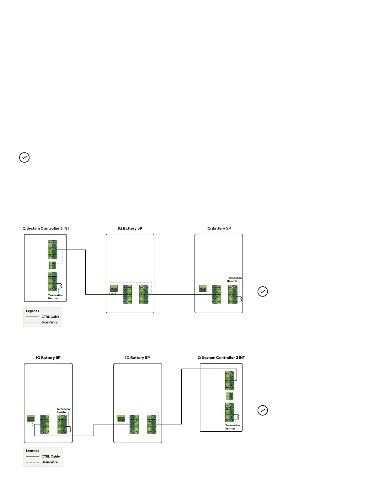
Sequence 1: IQ System Controller 3 INT → IQ Battery(s) 5P
Sequence 2: IQ Battery(s) 5P → IQ System Controller 3 INT
NOTE: Total length of CTRL wiring
across the system cannot exceed
75 meters to ensure system operates
as per specications.
NOTE: Total length of CTRL wiring
across the system cannot exceed
75 meters to ensure system operates
as per specications.
Control (CTRL) wiring
between system components
Control wiring guidance for the Enphase Energy System:
Refer to the following wiring sequences to understand the position
of header with termination resistor, wiring order, and drain wire
termination location.
NOTE: Ensure following guidelines are followed to avoid
failures during system commissioning:
• One header with termination resistor should be installed
on each component that is at the extreme end of the
control network.
• The drain wire should only be terminated on one end of
control wiring between system components
• It is recommended to terminate drain wire at the
component from which the control wiring for the section
is initiated
• Same conduits can be used for power and control wire
routing with Enphase recommended cables
Following are three indicative wiring sequences: