EasyManuals Logo

enphase IQ System Controller 3 INT User Manual

enphase IQ System Controller 3 INT
40 pages
To Next Page IconTo Next Page
To Previous Page IconTo Previous Page
Page #9 background imageLoading...
Page #9 background image
9
IQ System Controller 3 INT Quick Install Guide
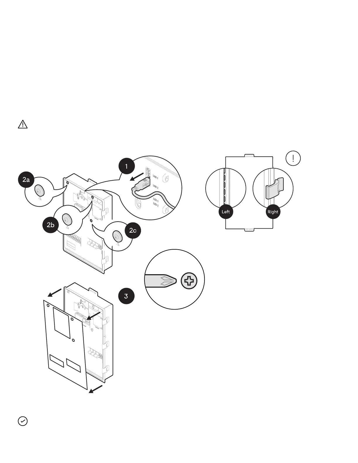
Step 5:
Opening the dead front
Before removing the dead front, ensure the IQ System Controller 3
INT is completely de-energized.
Risk of equipment damage. Do not wire the IQ System
Controller 3 INT when it is energized.
IQ System Controller 3 INT orientation
Philips screw #2
Torque: 1.4 N m
Section A - Mounting an IQ System Controller 3 INT
NOTE: Step 1 shown above may not be required during initial
installation as Cellular modem may not be connected.

Questions and Answers:

Question and Answer IconNeed help?

Do you have a question about the enphase IQ System Controller 3 INT and is the answer not in the manual?

enphase IQ System Controller 3 INT Specifications

General IconGeneral
Brandenphase
ModelIQ System Controller 3 INT
CategoryController
LanguageEnglish

Related product manuals