25
IQ System Controller 3 INT Quick Install Guide
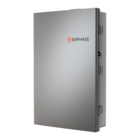
Wiring control (CTRL)
cable to headers
IQ System Controller 3 INT supports wired control connections.
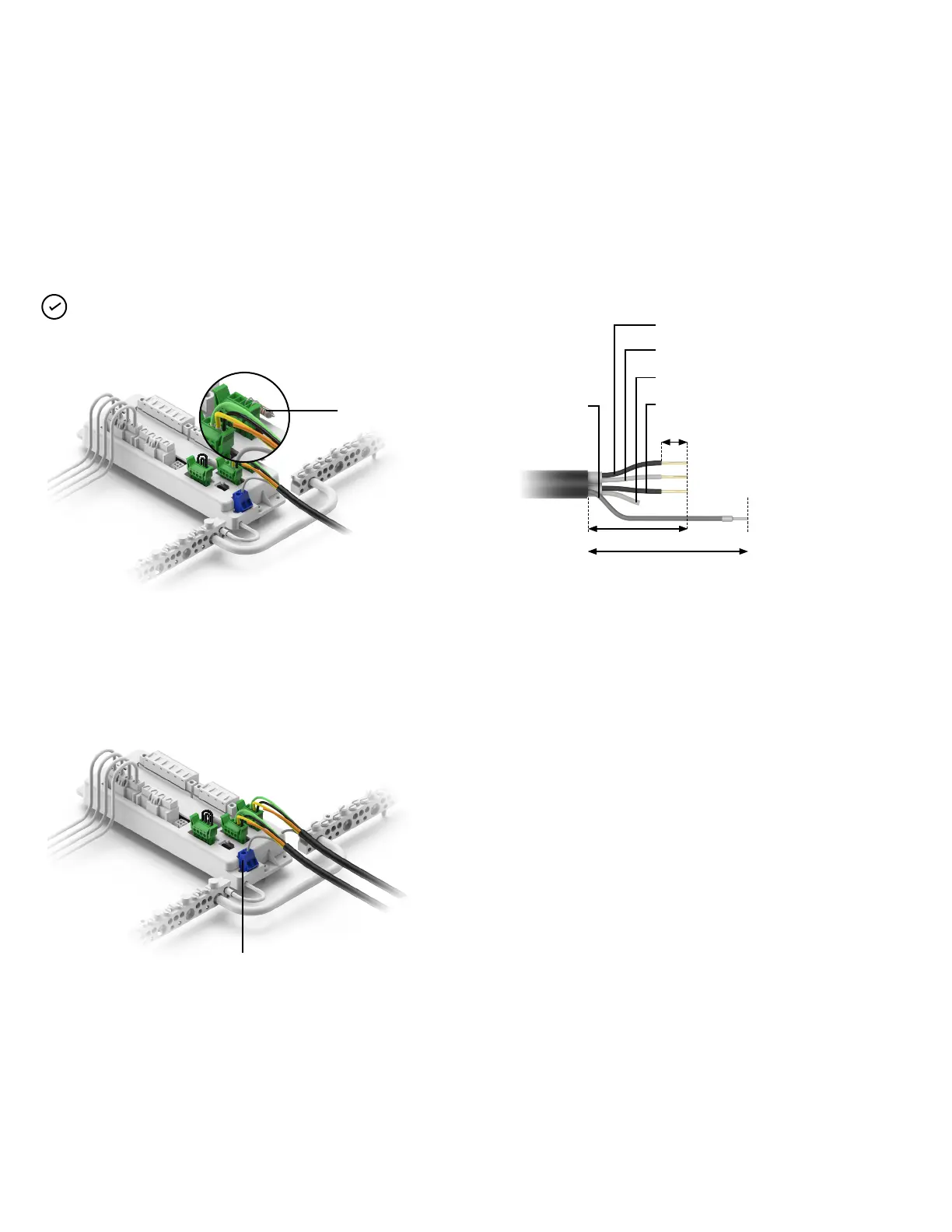
NOTE: Use Enphase recommended cables, headers and also refer
to local codes for any specic local requirements.
8 mm
CTRL (L)
CTRL (H)
(NA) to be trimmed
CTRL (G) - Ground
Drain wire
• Control wiring colours are indicative and might dier for
dierent manufacturers
• The control cable must be stripped to the recommended
dimensions as indicated above, and then connected to the
header
The tested and supported control cable make and models are:
Electra EAS7302PHV/EAS7502PHV or the LAPP 1270802.
Scenario 1: When IQ System Controller 3 INT is a terminal node for
the control network (at the end of the control cable loop), use a
connector with a termination resistor in the terminal port.
Scenario 2: When IQ System Controller 3 INT is not a terminal node
for the control network (in the middle of the control cable loop),
terminate the control wires on both the connectors.
Drain terminal
Section B - Wiring
Termination resistor
38 mm
76 mm or to be trimmed till jacket, when not
connected to drain terminal