2
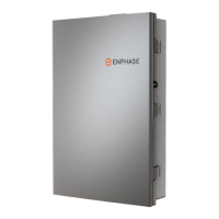
IQ System Controller 3 INT Quick Install Guide
Table of contents
Introduction
Section A
Mounting an IQ System Controller 3 INT
Tools/additional items required
Step 1: Plan a location for mounting the unit
Step 2: Minimum clearance
Step 3: Opening the door
Step 4: Mounting the IQ System Controller 3 INT
Step 5: Opening the dead front
Section B - Wiring
Internal view of IQ System Controller 3 INT
Power terminals
Recommended breaker selection
Drill conduits
Single-phase home
Field wiring of mains
Field wiring of loads
Field wiring one branch of single-phase PV
Field wiring single-phase battery and one branch
of single-phase PV
Field wiring two branches of single-phase PV
Field wiring two branches of single-phase PV
and single-phase IQ Battery
System eld wiring single-phase battery and
one branch of single-phase PV
Three-phase home
Field wiring of mains
Field wiring of loads
Field wiring three-phase PV
Field wiring three-phase PV and three-phase IQ Battery
Wiring control (CTRL) cable to headers
Control (CTRL) wiring between system components
AUX wiring: PV shedding/load control
Close dead front and install breaker ller plate
Connecting Cellular modem
System Shutdown (SSD) switch wiring
Energize IQ System Controller 3 INT
Operation
Safety
Revision history