8
IQ System Controller 3 INT Quick Install Guide
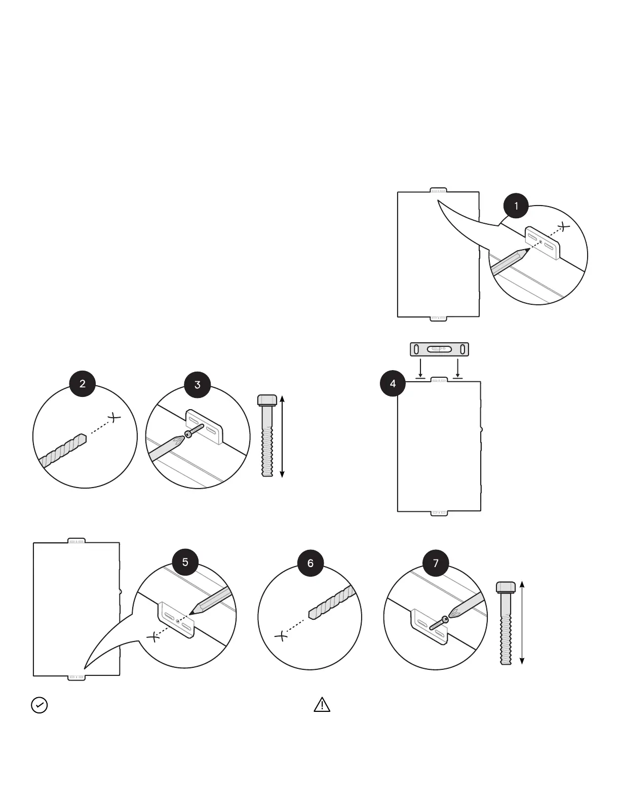
Step 4:
Mounting the IQ System
Controller 3 INT
Please note the following:
• Risk of electric shock. To maintain the warranty, do not modify
the dead front other than to remove or replace ller plates, as
needed.
• Place the IQ System Controller 3 INT on the wall so that the
mounting holes at middle of the mounting tabs are aligned with
the center of the stud. Mark the top center hole for predrilling
and keep the unit aside safely.
• Adhere to local standards. Use washers between fastener
heads and wall-mount bracket.
Ensure proper
alignment using
alignment indicator
M6
M6
80 mm
recommended
(depending on
wall thickness)
80 mm
recommended
(depending on
wall thickness)
Section A - Mounting an IQ System Controller 3 INT
NOTE: Use a drill bit extender for better access to mounting
holes during installation.
WARNING: Do not drill the conduit holes on the wall when the
unit is installed as it may lead to exposure of circuit boards to
heavy dust. Conduit holes to be marked separately on the unit
and wall for drilling.