IQ7+ and I Q7A Installation and Operation Manual - India
29 © 2023 Enphase Energy Inc. All rights reserved. August 2023
USM-00002-1.0
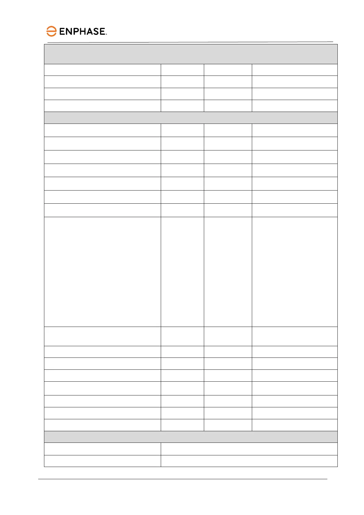
IQ7A-72-2-INT Microinverter parameters
Maximum short-circuit DC input current I
scmax
V 25
Maximum module Isc A 20
Maximum input power***
P
dcmax
W 550
Maximum apparent power S
VA 366
Rated power P
W 349
Nominal grid voltage
U
acnom
V 230
Minimum/maximum grid voltage U
acmin
/
U
acmax
V 184/276
Maximum output current l
A 1.59
Nominal frequency f
Hz 50
Minimum/maximum frequency f
f
Hz 45/55
Maximum units per single/multi-phase
20 A circuit
16 A/I
acmax
10 (L+N)/30 (3L+N)
For IQ Cable with 2.5 mm
2
stranded conductors and
using a 1.25 safety factor, 16
A per phase is calculated as
the maximum current
according to IEC 60364. The
safety factor applied may
vary based on local
regulations or the best
practices, also upon the
characteristic the OCPD
Protective class (all ports)
II
Total harmonic distortion
Power factor setting
1.0
Power factor range
cosphi 0.8 leading – 0.8 lagging
Inverter maximum efficiency
η
% 97.2
IS/IEC 61683 efficiency
η
IS
% 96.6
Inverter topology
Isolated (HF transformer)
Ambient air temperature range
°
°
Relative humidity range 4% to 100% (condensing)