IQ7+ and I Q7A Installation and Operation Manual - India
28 © 2023 Enphase Energy Inc. All rights reserved. August 2023
USM-00002-1.0
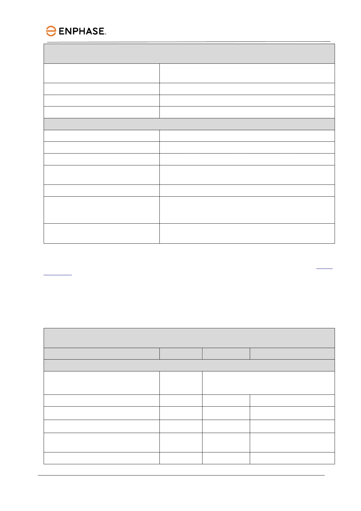
IQ7PLUS-72-2-INT Microinverter parameters
Enclosure Class II double-insulated, corrosion-resistant polymeric
IEC 62109-1, IEC-62109-2/IS 16221; IEC 61727
EN IEC 62109-1, EN IEC 62109-2
EMC EN IEC 61000-3-2, 61000-3-3, 61000-6-2, 61000-6-3, EN IEC
Product labelling CE and BIS
Advanced grid functions
2
Power export limiting (PEL), Phase imbalance management
(PIM), Loss of phase detection (LOP), Power factor control Q
Microinverter communication
Power line communication (PLC) 110−120 kHz (Class B), narrow
1. No enforced DC/AC ratio and maximum input power. Modules can be paired if the maximum input voltage is not exceeded and the
maximum input current of the inverter at the lowest and highest temperatures is respected. See the compatibility calculator at module
compatibility.
2. Some of these functions require IQ Gateway Metered with current transformers (CTs) and/or IQ Relay installed.
*** The maximum input power values are recommended to address region-specific requirements.
IQ7A-72-2-INT Microinverter specifications
IQ7A-72-2-INT Microinverter parameters
Typical module compatibility
1
66-cell/132-half-cell
72-cell/144-half-cell
Minimum/maximum input voltage
Startup input voltage U
dcstart
V 33
Rated input voltage U
dc,r
V 40.5
Minimum/maximum MPP voltage U
mppmin
/U
mppmax
V 38/43
Minimum/maximum operating voltage