RPS Deployment Strategies
1-4 Introduction
RPS Deployment Strategies
TheRPScanbedeployedinavarietyofsituationswithmission‐criticalapplications.
For example:
•ForuseinavoiceanddatanetworkwhereswitchesareconnectedtoIPphonesand
PCs.ConnectinganRPStotheswitchescanpreventvoicenetworkfailurescausedby
switchfailures.
•Foruseintraditional
data10/100/1000Ethernetswitchescarryingmission‐critical
data.
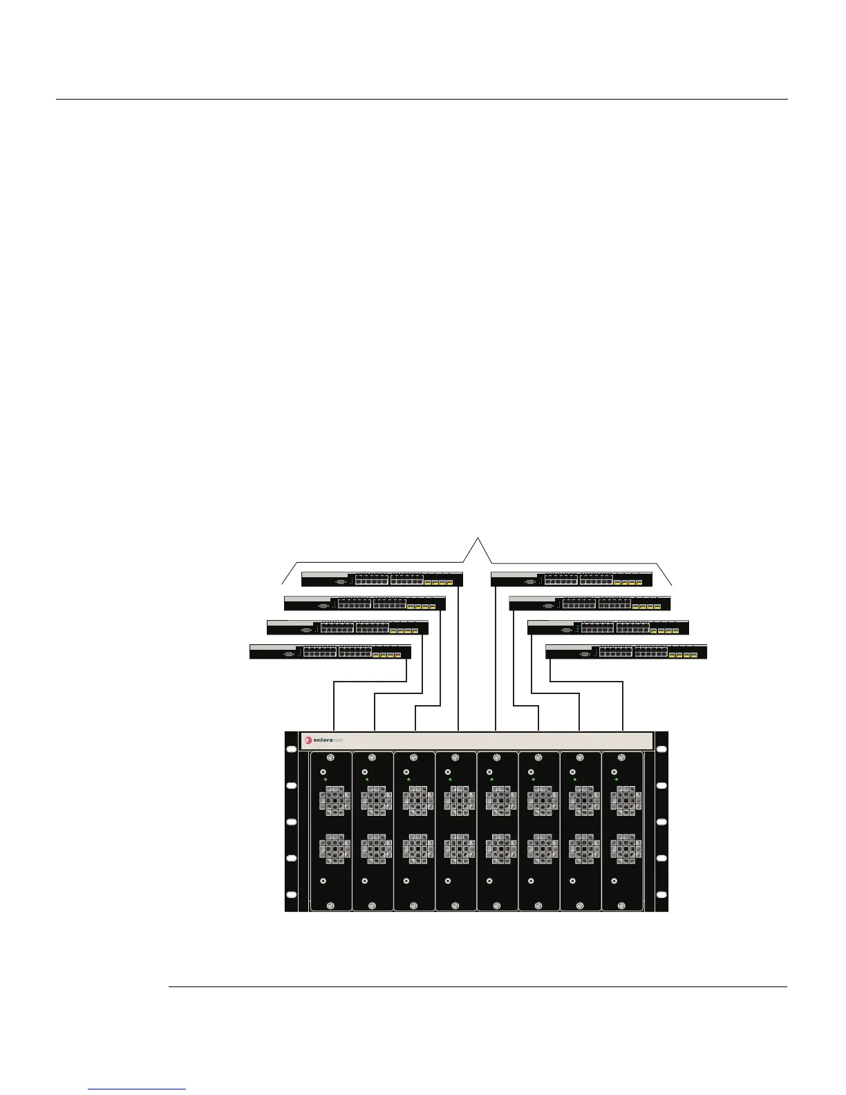
TheseapplicationswouldtypicallyuseoneRPSto supportuptoeightSecureStackC2
switchdevicesasshowninFigure 1‐5.IfaSecureStackC2switchdeviceexperiencesan
internalpower‐supplyfail ure,thefollowingoccurs:
1. TheSecureStackC2switchdeviceinternalDC
‐powersourceisimmediatelyswitched
overfromtheinternalDC‐powersupplytotheRPSDC‐powerinput.
2. TheSecureStackC2switchdevicesavesthisstatusinformationforfutureretrieval,if
necessary.
Figure 1-5 RPS Supporting a Group of Switches (up to eight)
1 C2RPS-CHAS8 chassis (front view with eight PSMs) 3 SecureStack C2 Ethernet switches
2 C2RPS-PSM Cables for 12 Vdc and status
information from PSMs
À
Â
Á
C2RPS-CHAS8
C2RPS-PSM
Power
C2RPS-PSM
Power
C2RPS-PSM
Power
C2RPS-PSM
Power
C2RPS-PSM
Power
C2RPS-PSM
Power
C2RPS-PSM
Power
C2RPS-PSM
Power
CONSOLE
1
2
23
24
21 22 23 24
CPU
UP
RPS
MASTER
DOWN
C2G124-24
CONSOLE
1
2
23
24
21 22 23 24
CPU
UP
RPS
MASTER
DOWN
C2G124-24
CONSOLE
1
2
23
24
21 22 23 24
CPU
UP
RPS
MASTER
DOWN
C2G124-24
CONSOLE
1
2
23
24
21 22 23 24
CPU
UP
RPS
MASTER
DOWN
C2G124-24
CONSOLE
1
2
23
24
21 22 23 24
CPU
UP
RPS
MASTER
DOWN
C2G124-24
CONSOLE
1
2
23
24
21 22 23 24
CPU
UP
RPS
MASTER
DOWN
C2G124-24
CONSOLE
1
2
23
24
21 22 23 24
CPU
UP
RPS
MASTER
DOWN
C2G124-24
CONSOLE
1
2
23
24
21 22 23 24
CPU
UP
RPS
MASTER
DOWN
C2G124-24