ENVIRO-TEC
16
Face Area, Free Area and Filter Sizes
NOTES:
1. Face and free areas are in square feet [square meters].
2. Filter sizes are in inches [millimeters].
COIL FACE 1" THROWAWAY1" PLEATED2" PLEATED
AREA FACE AREA GROSS MEDIA AREA GROSS MEDIA AREA
06 1.56 [0.15]
(1) 16 x 16
[406 x 406] 1.62 [0.15] 4.0 [0.37] 5.4 [0.50]
08 2.08 [0.19]
(1) 16 x 20
[406 x 508] 2.04 [0.19] 4.8 [0.45] 6.8 [0.63]
10 2.50 [0.23]
(1) 16 x 25
[406 x 381] 2.57 [0.24] 6.0 [0.56] 8.5 [0.79]
12 3.02 [0.28]
(2) 16 x 16
[406 x 406] 3.23 [0.30] 8.0 [0.74] 10.4 [0.97]
14 3.54 [0.33]
(1) 16 x 16 & (1) 16 x 20
(1)
[406 x 406] & (1) [406 x 508]
3.65 [0.34] 8.8 [0.82] 12.2 [1.13]
16 4.06 [0.38] (2) 16 x 20 [406 x 508] 4.08 [0.38] 9.6 [0.89] 13.4 [1.24]
18 4.58 [0.43]
(1) 16 x 20 & (1) 16 x 25
(1) [406 x 508] & (1) [406 x 635]
4.61 [0.43] 10.8 [1.00] 14.3 [1.33]
20 5.00 [0.46]
(2) 16 x 25
[406 x 635] 5.14 [0.48] 12.0 [1.11] 17.0 [1.58]
NOMINAL FILTER SIZES
SIZE
VALVES & PIPING
No formal maintenance is required on the valve package
components most commonly used with fan coil units
other than a visual inspection for possible leaks in the
course of other normal periodic maintenance. In the
event that a valve should need replacement, the same
precautions taken during the initial installation to protect
the valve package from excessive heat should also be
used during replacement. In some cases, the valve
actuator may fail and usually can be replaced without
removing valve body from piping.
DRAIN
The drain should be checked before initial start-up and
at the beginning of each cooling season to assure that
the lines are clear. If it is clogged, steps should be taken
to clear the debris so that condensate will ow easily.
Periodic checks of the drain should be made during the
cooling season to maintain a free owing condensate.
Should the growth of algae and/or bacteria be a
concern, consult an air conditioning and refrigeration
supply organization familiar with local conditions for
chemicals available to control these agents. If cleaners
are used, they should be compatible with the materials
of construction for the coil and drain pan.
FILTERS
This unit is equipped with a standard 1” throwaway
lter most commonly used on fan coil units should be
replaced on a regular basis. The time interval between
each replacement should be established based on
regular inspection of the lter and should be recorded
in the log for each unit. At a minimum, lters should
be inspected monthly and replaced if needed. Refer to
the Filters chart for recommended lter size for each
product type and size. If the replacement lters are not
purchased from the factory, the lters used should be
the same type, size and MERV rating as that furnished
from or recommended by the factory. Optional 1” and 2”
pleated lters are available and can be used in this unit.
Contact the local Sales Representative for the correct
lter upgrade specication and availability. Consult the
factory for applications using lter types other than the
factory standard or optional product.
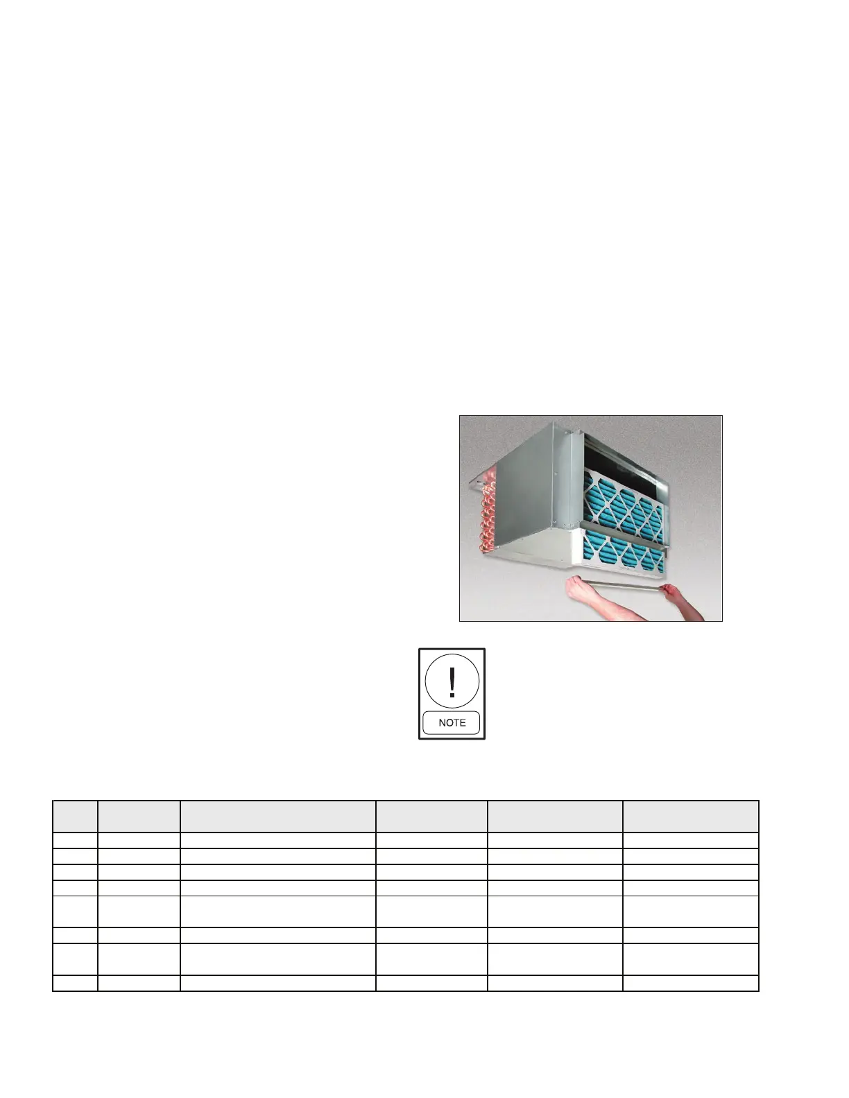
FILTER REPLACEMENT
To replace the lter(s), unscrew the thumb screws
located at the bottom of the lter bracket a few turns
until the lter tray freely slides out. Slide out the used
lter(s) and replace with the new one(s). Reattach the
lter tray to the lter bracket with the supplied thumb
screws.
The lter tray is fully adjustable and
can be rotated 180 degrees if necessary
to ensure a snug t between the lter
and the lter bracket.