ENVIRO-TEC
26
• Ensure no wires are oating loosely in product.
Verify all wires are connected properly on relay
board.
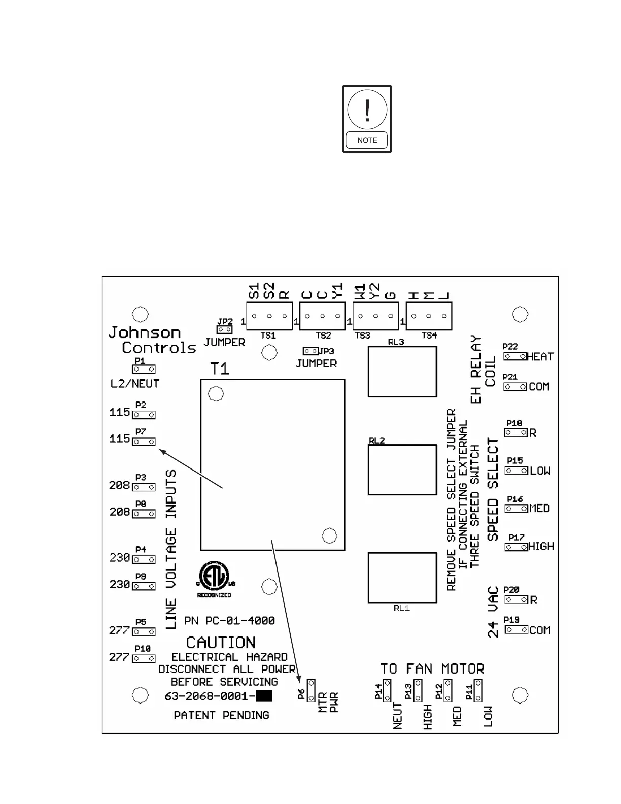
• Measure input voltage on relay board as indicated
below:
P1– P2 = 115V
P1– P3 = 208V
P1– P4 = 230V
P1– P5 = 277V
• Ensure “MTR PWR” is connected to correct volt-
ages (115V/P7 or 208V/P3 or 230V/P4 or 277V/
P5). See Figure 4 below.
TROUBLE SHOOTING GUIDE FOR FAN COIL RELAY BOARD
Connect jumper wire
between 2 points for
motor power or 208V,
230V, 277V
Motor power can only be connected
to one voltage.
P7– P6 = 115V
P8– P6 = 208V
P9– P6 = 230V
P10– P6 = 277V
FIG. 4 - FAN COIL RELAY BOARD WITH MOTOR POWER CONNECTIONS
LD13950