ENVIRO-TEC
19
HP with ECM Variable Speed Motor Balancing Instructions
See Fig.1 for PCB layout
ELECTRICAL SHOCK HAZARDS. All
power must be disconnected prior to installa-
tion and serving this equipment. More than
one source of power may be present. Discon-
nect all power sources to avoid electrocution
or shock injuries.
Commissioning
1. Verify that there is 22 to 28 VAC across terminals 15
and 16.
2. Verify that there is 15 VDC across terminals G (+) and
COM (-).
Manual Balancing
1. Verify that the jumper is in the “MAN” position (shipped
from factory in Manual mode).
2. Connect voltmeter to wire loop VDC (+) and wire loop
COM (-).
3. Determine the DC voltage for required airow from the
Fan Calibration Curve shown in Fig. 2 and supplied on
the side of the equipment. Use the bottom (5 to 10 volts
DC) scale on the chart.
4. Using an insulated 1/8” at bladed screwdriver, adjust
the manual speed potentiometer, labeled SPD, to obtain
the required voltage. Clockwise increases airow,
counterclockwise decreases airow.
5. Do not set the voltage lower than 5.0 VDC or higher than
10.0 VDC or motor may experience starting problems.
(For units shipped prior to April 2011, do not set voltage
lower than 5.1 VDC or higher than 9.9 VDC).
6. Do not set the balance voltage outside limits of the volt-
age/CFM curve or erratic motor operation and eventual
failure may result.
Remote Balancing
1. Relocate the jumper into the REM position.
2. Determine the DC voltage for required airow from
the Fan Calibration Curve supplied on the side of the
equipment. Use the top (2 to 10 Analog Input Volts
DC) scale on the chart.
3. Remotely adjust the external voltage source to the
desired volts DC for required airow.
4. Do not operate motor at control voltage lower than 2.0
VDC or higher than 10.0 VDC or motor may experi-
ence starting problems. (For units shipped prior to April
2011, do not set voltage lower than 2.1 VDC or higher
than 9.9 VDC).
5. Do not set the balance voltage outside limits of the
voltage /CFM curve or erratic motor operation, and
eventual failure may result.
Status LED
When the motor is running, the LED alternates between
CFM and RPM indications. In the RPM mode, LED turns
on for a period of approximately 220 microseconds at a rate
of 36 pulses per revolution. This mode lasts for ten seconds.
Due to the rapid rate, LED will appear to be dimly lit, not
ashing. As RPM is increased, brightness will increase. In
the CFM mode, the LED will ash slowly, and at maximum
brightness, once for every 100 CFM. Accuracy is +/- one
ash. LED will then return to RPM mode, and cycle will
repeat.
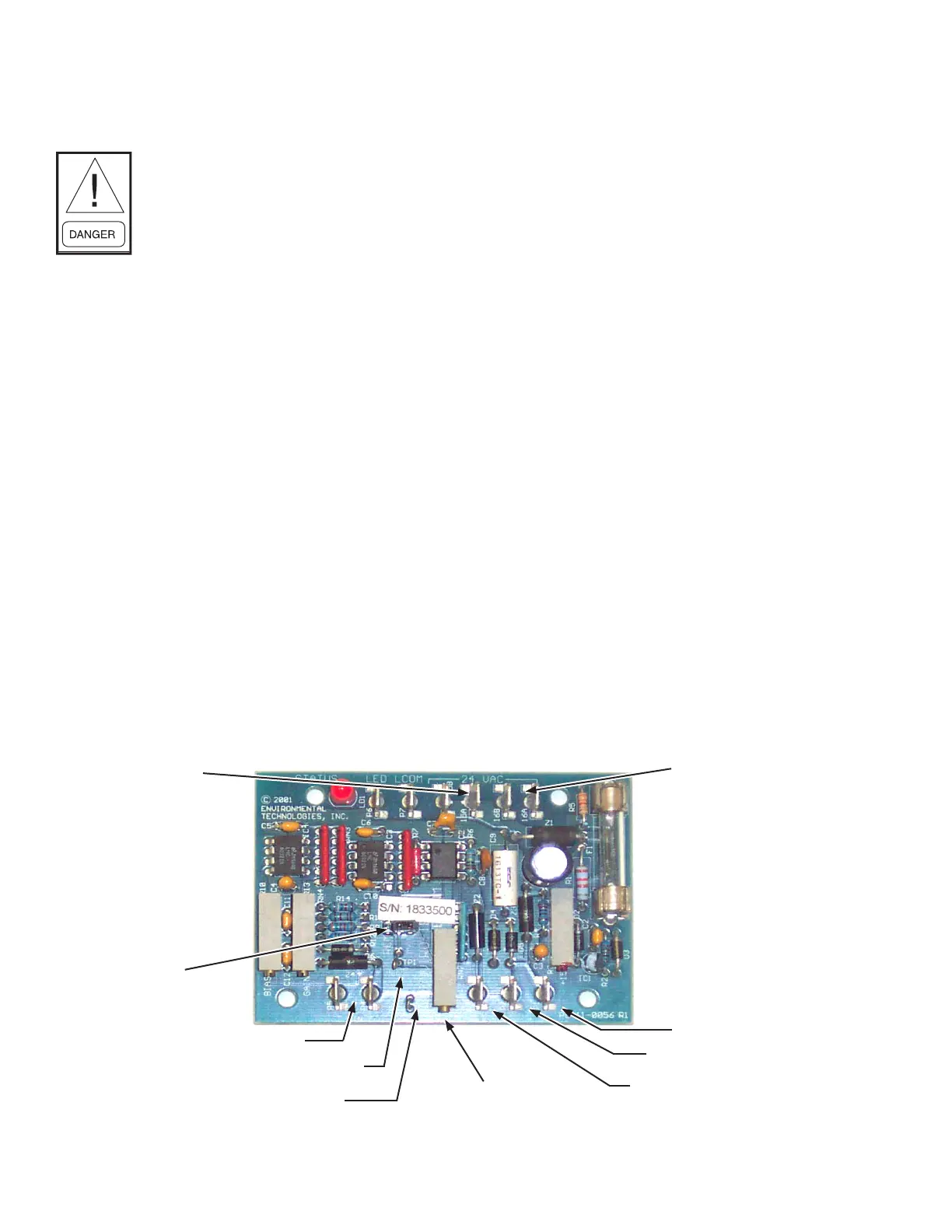
FIG. 1 - PCB LAYOUT
LD14390
24 volts AC
16 A & B
24 volts AC
15 A & B
“G” actvation line
Signal common
PWM output
Manual speed
adjustment
(SPD)
Comon test loop
VDC test loop
Analog input 2 - 10 VDC
Remote
manual
jumper
 Loading...