ENVIRO-TEC
7
PLENUM BOX REMOVAL
In most cases this unit is fully serviceable without the
need for removal of the plenum box. However should
the need arise, the plenum box is easily removable by
removing the screws attaching the plenum box to the
sides, top and rear of the coil casing.
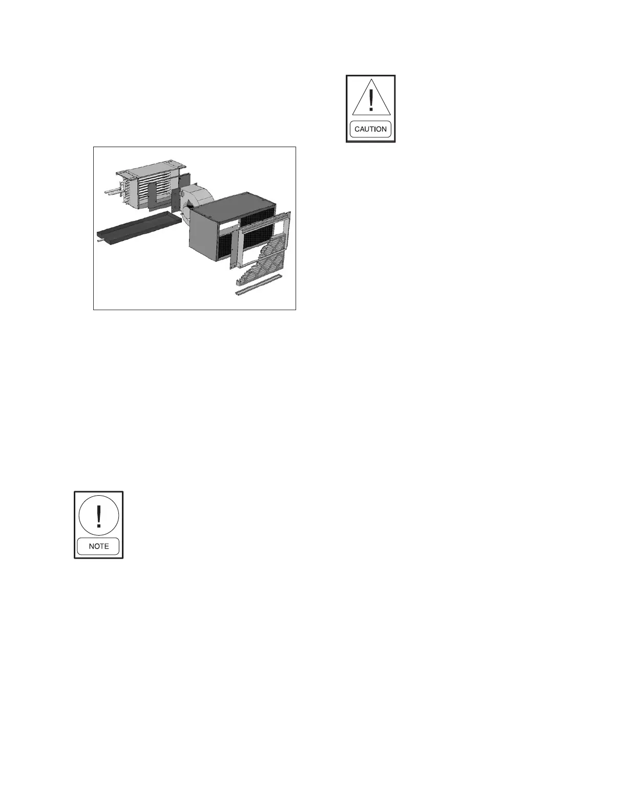
COIL HANDING
This unit features a eld reversible coil assembly should
the need arise upon installation to change the handing of
the coil. To change the coil handing, remove the plenum
box (if applicable) from the coil by removing all screws
to the coil casing. Next, remove the fan(s), fan deck,
and top and bottom casings from the coil. Rotate the
coil. Replace the bottom coil casing in the top coil casing
position and the top coil casing in the bottom coil casing
position and reattach the fan deck, fan(s) and plenum
box (if applicable) in the original locations.
The leaving air side of the n pack
will remain the same after changing
the coil handing.
COILS
All fan coils are available in 2 or 4 pipe congurations.
Heating and cooling coils are eld reversible for right
or left side connections. On units with water coils, the
maximum water pressure applied to the unit should
never exceed 300 PSIG at 200°F. On units with steam
heating coils, the maximum steam pressure applied
to the unit should never exceed 15 PSIG. The drain
piping and steam trap should be sized and routed to
allow for proper condensate ow. (Minimum ambient
temperature 35°F. Coils may freeze.)
PIPING CONNECTIONS
Toxic residues and loose particles
resulting from manufacturing and
eld piping techniques such as joint
compounds, soldering ux, and metal
shavings may be present in the unit
and the piping system. Special con-
sideration must be given to system
cleanliness when connecting to solar,
domestic or potable water systems.
Submittals and Product Catalogs detailing unit operation,
controls, and connections should be thoroughly
reviewed BEFORE beginning the connection of the
various cooling and/or heating mediums to the unit.
All accessory valve packages should be installed as
required, and all valves should be checked for proper
operation.
If coil and valve package connections are to be made
with “sweat” or solder joint, care should be taken to
assure that no components in the valve package are
subjected to a high temperature which may damage seals
or other materials. Many two-position electric control
valves, depending on valve operation, are provided with
a manual-opening lever. This lever should be placed
in the “open” position during all soldering or brazing
operations. Valve bodies should be wrapped with a wet
rag to help dissipate heat encountered during brazing.
Use a brazing alloy to make connections such as BCup-
2. Soft solder is not recommended.
If the valve package connection at the coil is made with
a union, the coil side of the union must be prevented
from twisting (“backed up”) during tightening to prevent
damage to the coil tubing. Over-tightening must be
avoided to prevent distorting the union seal surface
and destroying the union. In the case of eld installed
valves and piping, the chilled water valve cluster (or
expansion valve on DX units) should be installed in
such a way that any dripping or sweating is contained
in the auxiliary drain pan or other device. Valves and
TXV’s should be secured or supported to avoid damage
to coil headers or distributor tubes.