ENVIRO-TEC
8
DUCTWORK CONNECTIONS
All ductwork and/or supply and return grilles should
be installed in accordance with the project plans and
specications. If not included on the unit or furnished
from the factory, ENVIRO-TEC supply and return
grilles are available in a variety of types.
All units must be installed in non-combustible areas.
Some models are designed to be connected to ductwork
with a MINIMUM amount of external static pressure.
Consult the approved submittals and the product catalog
for unit external static pressure limitations.
Units provided with outside air for ventilation should
have some form of low temperature protection to
prevent coil freeze-up. Outside air should be pretreated
for best results.
It should be noted that none of these methods would
adequately protect a coil in the event of power failure.
The safest method of freeze protection is to use glycol
in the proper percent solution for the coldest expected
air temperature. Consult glycol supplier literature for
correct solution ratios.
The manufacturer assumes no responsibility for
undesirable system operation due to improper
design, equipment or component selection, and/or
installation of ductwork, grilles, and other eld supplied
components.
ELECTRICAL CONNECTIONS
ELECTRICAL SHOCK HAZARDS.
All power must be disconnected prior
to installation and serving this equip-
ment. More than one source of power
may be present. Disconnect all power
sources to avoid electrocution or shock
injuries.
The electrical service to the unit should be compared to
the unit nameplate to verify compatibility. The routing
and sizing of all conduit, and the type and sizing of all
wiring and other electrical components such as circuit
breakers, disconnect switches, etc. should be determined
by the individual job requirements and should not be
based on the size and/or type of connection provided
on the equipment. All installations should be made in
compliance with all governing codes and ordinances.
Compliance with all codes is the responsibility of the
installing contractor. The unit nameplate lists the unit
electrical characteristics such as the required supply
voltage, fan and heater amperage and required circuit
ampacities. The unit-wiring diagram shows all unit and
eld wiring. Since each project is different and each
unit on a project may be different, the installer must
be familiar with the wiring diagram and nameplate on
the unit BEFORE beginning any wiring. This unit is
not acceptable for installation in hazardous/explosive
areas.
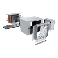
CONTROL ENCLOSURE
The optional electrical control enclosure provides access
to the electrical compartment. This compartment houses
all electric heat and control components. Terminal strips
are furnished for simple power and control wiring
connections. Multiple knockouts allow wiring entries
from either side of the compartment.
All components furnished for eld installation, by either
the factory or the controls contractor should be located
and checked for proper function and compatibility. All
internal components should be checked for shipping
damage and all electrical connections should be
tightened to minimize problems during start-up.
Any devices such as fan switches or thermostats
that have been furnished from the factory for eld
installation must be wired in strict accordance with the
applicable wiring diagrams. Failure to do so could result
in personal injury or damage to components and will
void all manufacturers’ warranties.
The fan motor(s) should never be controlled by any
wiring or device other than the factory furnished switch
or thermostat/switch combination, without factory
authorization.
All eld wiring should be done in accordance with
governing codes and ordinances. Any modication of
the unit wiring without factory authorization will result
in voiding of all factory warranties and will nullify any
agency listings.
The manufacturer assumes no responsibility for any
damages and/or injuries resulting from improperly eld
installed or wired components.
 Loading...