16
DR1206/2206/3206/2210/3210N-DDB/DDS:
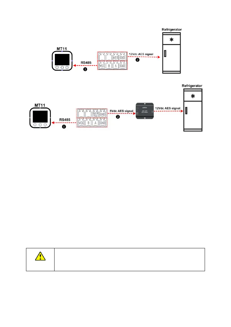
❶ RS485 Communication cable
CC-RS485-RS485-3.81-4P-150 (Included)
CC-RS485-RS485-3.81-4P-1000 (Optional)
CC-RS485-RS485-3.81-4P-2000 (Optional)
The remote meter operations refer to the MT11 user manual.
The controller only provides one AES signal control. A practical consideration is
needed for the specific application (Check the "1.5 AES Signal output port instruction"
for more information).
Step6: Power on the controller
1) Firstly, turn on the BATT2 safety switch and check the BATT2 charging indicator
status.
2) Then, turn on the BATT1 safety switch and check the BATT1 charging indicator
status (Check the "3. Display Units" for more information).
3) Lastly, connect the PV array circuit breaker.
If the controller is not operating properly or the battery indicator on
the controller shows an abnormality, please refer to 4.2
"Troubleshooting."