the BATT2 system voltage identification error.
While wiring the controller, do NOT connect the breaker or fuse.
Ensure that the electrode polarity is correctly connected.
A fuse whose current is 1.25 to 2 times the rated current of the
controller must be installed on the battery side with a distance
from the battery not greater than 150mm.
If an inverter is connected to the system, connect the inverter
directly to the battery.
Step3:Grounding❹
DR N series is a common-negative controller. All the negative terminals of the PV
array and battery can be grounded simultaneously, or any one of the negative will be
grounded. However, according to the practical application, all the negative terminals
of the PV array and battery needn't be grounded. However, the grounding terminal on
the controller's shell must be grounded. It may effectively shield the electromagnetic
interference from the outside and prevent electric shock to the human body.
A common-negative controller for common-negative systems, such
as a motorhome, is recommended. However, the controller may be
damaged if some common-negative equipment is used and its
positive electrode is grounded in the common-negative system.
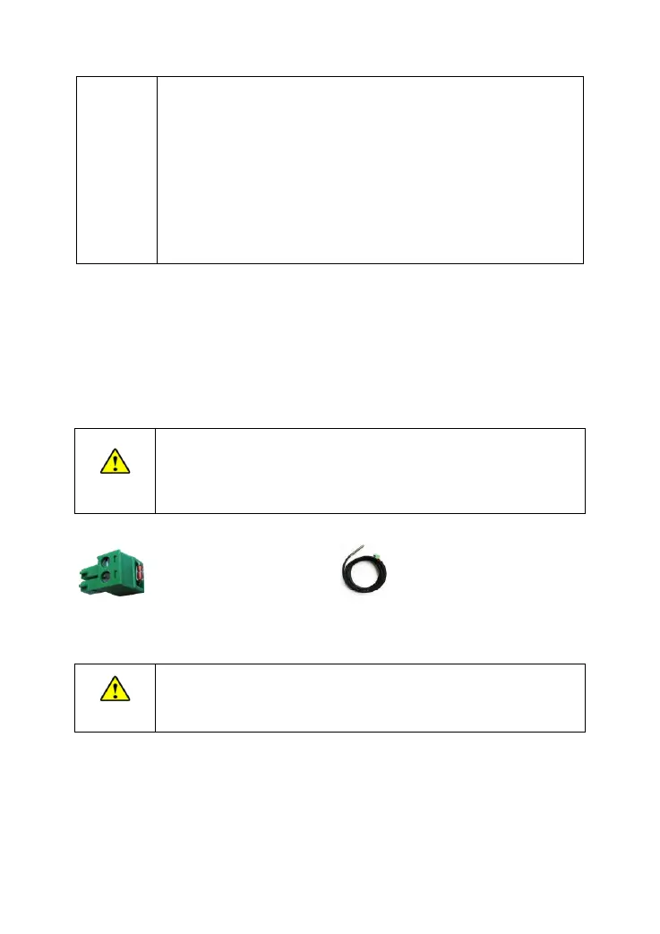
Step4: Connect the remote temperature sensor cable❺
(Model:RT-MF58R47K3.81A) (Model:RTS300R47K3.81A)
Connect the remote temperature sensor cable to the port ❹ and place the other end
close to the BATT1.
Suppose the remote temperature sensor is not connected to the
controller. In that case, the default temperature for battery charging or
discharging is 25℃ without temperature compensation.
Step5: Connect the remote meter MT11❻ and AES signal of the refrigerator❼
DR1106/2106/3106N-DDB/DDS:
Remoter temperature sensor