7
How to adjust the settings
Decrease the rotation speed if you notice:
• Increased wear to the drill bit, the hammer and the drill pipes
• Increased stresses to the feed and rotation unit
Increase the rotation speed if you notice:
• Poor drilling output
• Uneven rotation
• Uneven wear on buttons
Feed
The purpose of the feed is to keep the shank of the drill bit
pressed into the hammer while drilling.
Recommended settings
The feed force often needs to be corrected during drilling, de-
pending on the rock formation and the weight of the drill string.
The deeper the hole the less feed force is required, as the drill
string gets heavier. In very deep holes the drill string is actually
being held up to compensate for the heavy string. This is called
negative feeding or a holdback function.
A rough guide to drill pipe weights for different sizes of DTH-
hammer are given in the table.
Too low a feed force could harm the equipment or even lead to
loss of equipment. Triple lead thread by design to loosen chuck,
and when drilling, applying enough force is mandatory.
A tip for finding the setting force is to increase the feed force until
the bit is having a hard time to rotate, then you should cut down
the feed force until the bit rotates smoothly.
Recommended feed force
Air pressure (bar) Feed force (kN) Feed force (lbs)
10 7 1570
15 10 2250
20 14 3150
25 17 3820
30 20 4500
How to adjust the settings
Decrease the feed force if you notice:
• Rotation is jerky, uneven or completely stopped
• Hole deviation
• The rig is unstable and repositioned
If you carry on drilling with a feed force that is too high you will
experience reduced capacity. You will also expose the drill string
to severe bending stresses and possibly harm the rotation unit
and feed beam.
Increase the feed force if you notice:
• Vibrations
• Poor drilling results
• Increased wear to splines (The splines are the steel channels in
-
side the driver chuck that the bit shank holds on to while rotating).
If the feed force is not correctly set it will make the drill bit come
out of rhythm in relation to the air cycle inside the hammer. This
will increase the wear on the hammer.
Observing the drill string is the key to correctly adjusting the feed
force. Aim for a constant, even rotation speed with no jamming
and a steady penetration.
Flushing
If the cuttings are not removed, the drill bit will re-crush already
crushed material. This is a waste of energy and will reduce the
capacity of the drill. Flushing media are air, water and foam.
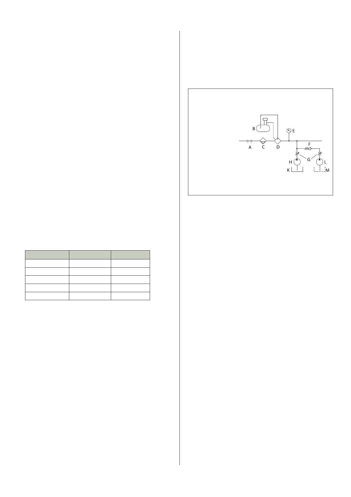
Flow chart for water flushing
A = Main inlet valve on drill rig
B = Container for air tool oil
C = Filter
D = Lubricator valve
E = Pressure gauge
F = Check valve
G = Valves
H = Water pump
K = Water tank
N = Compressor
O = DTH-hammer
Optional
L = Separate foam pump
M = Separate foam tank
Unlike the percussion pressure, the rotation and the feed, flushing
is not a parameter you can control individually. If the operator
experiences trouble with insufficient flushing he (or she) can
either reduce the penetration rate by cutting down the percussion
pressure or try another flushing medium. The flushing capacity
depends on gravity, particle size and particle shape. The need
for flushing is greatest if the cuttings consist of heavy, large and
spherical particles. In those cases you could try to use water or
foam to help the air to lift the cuttings up to the surface.
Water
Water controls the dispersion of dust when drilling dry holes.
As an example, only 2–6 litres of water per minute (at 18 bar air
pressure), injected into the main air line, is sufficient to control
the dust when drilling with for example the COP M6 hammer. Too
much water injection will have a very negative influence on the
penetration rate of the hammer.
A rule of thumb is to add 0,25 litres of water per m
3
compressed
air. The occurrence of water in the drill hole is common. Both “too
little” and “too much” can be troublesome. Too little water tends
to bind the drill cuttings into a paste, which sticks to the drill pipes
or the hole wall and can easily form plugs. The problem can be
lessened by adding water to the flushing air, thus increasing the
fluidity of the cuttings. Remember to increase the lubrication dos-
age when injecting water into the flushing air!
Foam
Foam can be used in DTH drilling to improve the flushing perfor-
mance (especially in non-consolidated formations). It does this by
“lifting up” the cuttings out of the hole, and also has the desirable
effect of sealing the hole walls. Foaming concentrate is pumped
into the compressed air line in the form of a mixture (a mixture of
0,5–2 percent concentrate/water is recommended).
The mixture is injected into the main air line by means of a high
pressure pump. The minimum pressure for the water-injection
pump is 30 bar and the minimum flow is 20 litres per minute.
After drilling with foam, it is recommended that any foam left
in the hammer should be flushed out of the hammer to prevent
corrosion. This is done by injecting water only into the air, and so
flushing the foam out the hammer. Oil should then be poured into
the drill string and the hammer operated for a few minutes before