13
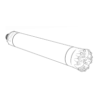
Casing (diameter)
Wear limit COP M6, COP M7 and COP M8:
COP M6: min. 135 mm.
COP M7: min. 165 mm.
COP M8: min. 183 mm.
Action if worn out:
Replace or rebuild hammer with an E-kit.
Comments:
Measure the diameter along the full length of the casing, with the
exception of the outermost 100 mm at each end.
100 mm
100 mm
Ø
Bit bushing (inside diameter)
Ex. bit bearing for COP M6, COP M7 and COP M8:
Wear limit:
A-B ≤ 0,4 mm
Action if worn out:
Replace.
ØA
Comments:
Measure the bit bushing at
its waist.
Piston/casing
COP M6, COP M7 and COP M8
Wear limit:
Diametric clearance: max. 0,30 mm
ØA – ØB ≤ 0,30 mm
Action if worn out:
Replace.
Comments:
Outside diameter of piston should be measured at the sealing sur-
face of the piston.
ØA
ØB
ØB
Piston/control tube
Ex. control tube for COP M6, COP M7 and COP M8:
Wear limit:
Diametric clearance: max. 0,30 mm
ØA-ØB ≤ 0,30 mm
Action if worn out:
Replace.
ØA
ØB
Comments:
Inside diameter of the
piston against outside
diameter of the con-
trol tube.
Check valve
Wear limit:
Valve seat worn or damaged.
Action if worn out:
Replace.
Comments:
Tightness of check valve can be tested
by pouring a small amount of oil into
the valve with the hammer in vertical
position. If the lubricant passes through
the check valve you should replace it.
Wear to the driver chuck
and casing
Since the driver chuck and hammer casing are “sand-blasted”
continuously by large volumes of abrasive cuttings during drill-
ing, they eventually become worn out. The areas adjacent to the
cuttings grooves in the drill bit will be subjected to the most wear.
To prevent uneven wear of the hammer casing, therefore, the
driver chuck and bit should be marked as shown in the figure,
before the chuck is lifted off the bit.
When fitting the driver chuck back on to the drill bit after grinding
or replacing a drill bit, its radial location on the bit shank should
be advanced by one spline section.
This will give a more even distribu-
tion of wear on the driver chuck
and hammer casing. If the driver
chuck is exposed to exceptionally
heavy wear, for example when
drilling in rock formations with
a high quartz content (granite,
quartzite etc.), it may be necessary
to turn the driver chuck by more than one spline section in order
to prevent the driver chuck and hammer casing from wearing out
too quickly. As a rule, the cuttings grooves in the bit should al-
ways be pointing towards the part of the driver chuck that is least
worn. Since the hammer casing has three thread inlets, the part of
the driver chuck that is worn the most can be located against the
part of the hammer that is worn the least.
Wear to the driver chuck and hammer casing should be checked
regularly, for example every time the bit is reground or changed.
When the hammer casing has to be changed, the driver chuck
must be replaced at the same time.