10
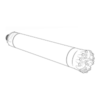
3) Remove the retaining rings and o-ring from the bit shank.
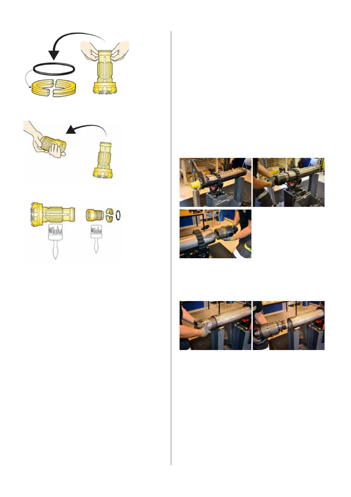
4) Remove the driver chuck from the bit.
5) Before assembling the drill bit and the driver chuck, follow the
instruction below:
• Smear the splines of the bit shank with copper or zink based
thread compound.
• Smear the o-ring of the bit retaing ring with silicon grease.
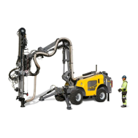
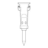
• Assemble the bit, driver chuck and retaing ring in the order that
is shown in the image to the left. It is very important to make sure
that the stop ring is located correctly, and that it faces the right
direc tion. Incorrect fitting will result in severe damage to the ham
-
mer.
• Smear the threads on the driver chuck with Epiroc’s thread
grease.
• Screw the bit and casing together. Note that there should be a
clearance of 0,1–0,4 mm between the driver chuck and the casing.
If there is no clearance, the end surface of the casing should be
ground down as necessary. Tighten the driver chuck with the aid
of the bit wrench.
Makeup torque
Simply put, this is the force you apply to properly tighten the
chuck to the hammer case and to tighten the top sub (backhead)
to the hammer case. ”Each threaded part will be tightened
individually” The design concept of the COP series of hammers
requires that enough sufficient internal compression be applied
by properly torqueing top (sub/backhead) and bottom (chuck) end
of the hammer, inner locking the proper internal hammer com-
ponents to specification provided in the technical manual called
make-up torque. A common practice in the field is to rely on the
torque from the rotary head to tighten these threaded joints. The
rotary can never apply enough torque for the specifications listed.
The use of a hammer breakout bench or other hydraulicaily opera
-
ted device is essential to reach the required specifications.
A good rule of thumb for torqueing/tightening the threaded joints
of the top sub and chuck is to apply a force of 750-1000 foot
pounds per inch of hammer diameter (40.5-54 Newton meters per
mm of hammer diameter).
Example: 8"/203 mm DTH hammer, such as COP M8
8" x 750-1000 ft. lbs = 6,000-8,000 ft. lbs
203 x 40-54 Nm = 8134.9-10,962
COP M series service
instructions
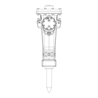
Disassembly of COP M series hammers
1) Remove backhead. Backhead
thread connection need to be
loosened up with a breakout
bench. Lift out the backhead,
weight of the COP M6 backhead
is around 7,4 kg (16.3 lbs), the
COP M7 29.2kg (64 lbs.) and the
COPM8 backhead is around 34.4
kg (75 1bs,)
Note: Upon removal of the backhead the compression ring may
become lodged in the backhead if debris or lack of maintenance
has occured. If present please re-insert backhead and tap with
brass bar to rattle loose the compression cone to release pres
-
sure.
2) Remove driver chuck, drill bit and bit retaining ring. The chuck
thread connection need to be loosened up either with breakout ta-
ble on drill rig before the hammer is removed, or with a breakout
bench.