General Settings
The adjustment of set points and the selection of an operation mode are performed via console ( Front Panel
Operation), interface ( Universal Interface) or analog/digital IO ( Ext. Control: AI-Interface).
In order of priority, commands which have been sent by interface come first, by analog/digital-IO come second and by
keyboard come third. For example, if the interface specifies the set point, the corresponding values will be sent to the
output, irrespective of other settings.
Another easy way to automate functions is offered by script control ( Script Control). A list of commands is saved to
the script memory and enables the user to change the chronological sequence of certain settings. The script memory
can be programmed via memory card or digital interface.
Measurement values of the latest output data are permanently available at all interfaces. Therefore, the present
output voltage can be read from the display or via digital interface, while the control of the unit is carried out via
analog/digital IO.
GENERAL SETTINGS
F
RONT
P
ANEL
D
ESCRIPTION
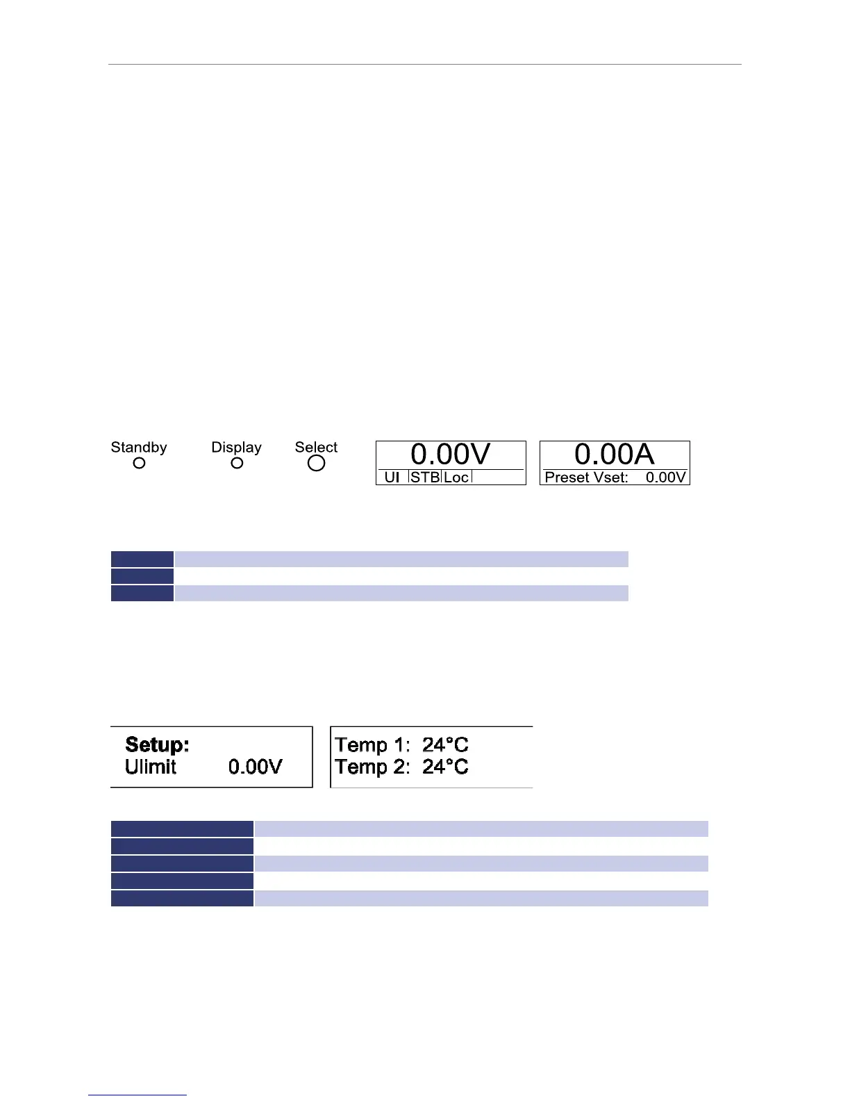
The picture above shows a schematic view on the front panel of the EPS/MP. There are 3 buttons to control the unit.
Basic functions of the control buttons:
Standby
release or lock the output, quit OVP
Display
short press: change displayed information, long press: change between main menu and setup menu
Select
press: change selected menu point, rotate: change selected value
C
ONFIGURATION
The configuration menu can be accessed by holding the button
Display
for at least 1 second. This opens a menu
where general settings of the unit can be changed. To browse through the different options, the button
Select
must
be pushed. To change a setting the button
Select
must be rotated.
Setup options:
U
0 V-V
max
; set maximum output current which is selectable at the front panel
OVP
0 V- 1.2 x V
max
; set over voltage protection activation value
AI-Mode
5 V/10 V; select the AI-control voltage range
Remember Last Setting
ON/OFF; activate or deactivate the settings memory after a power down the unit
The displayed temperature is the temperature of the heat sinks. Temperature 1 is the temperature of the PFC heat
sink and temperature 2 is the temperature of the power unit heat sink.