Front Panel Operation
12
O
PERATING MODES
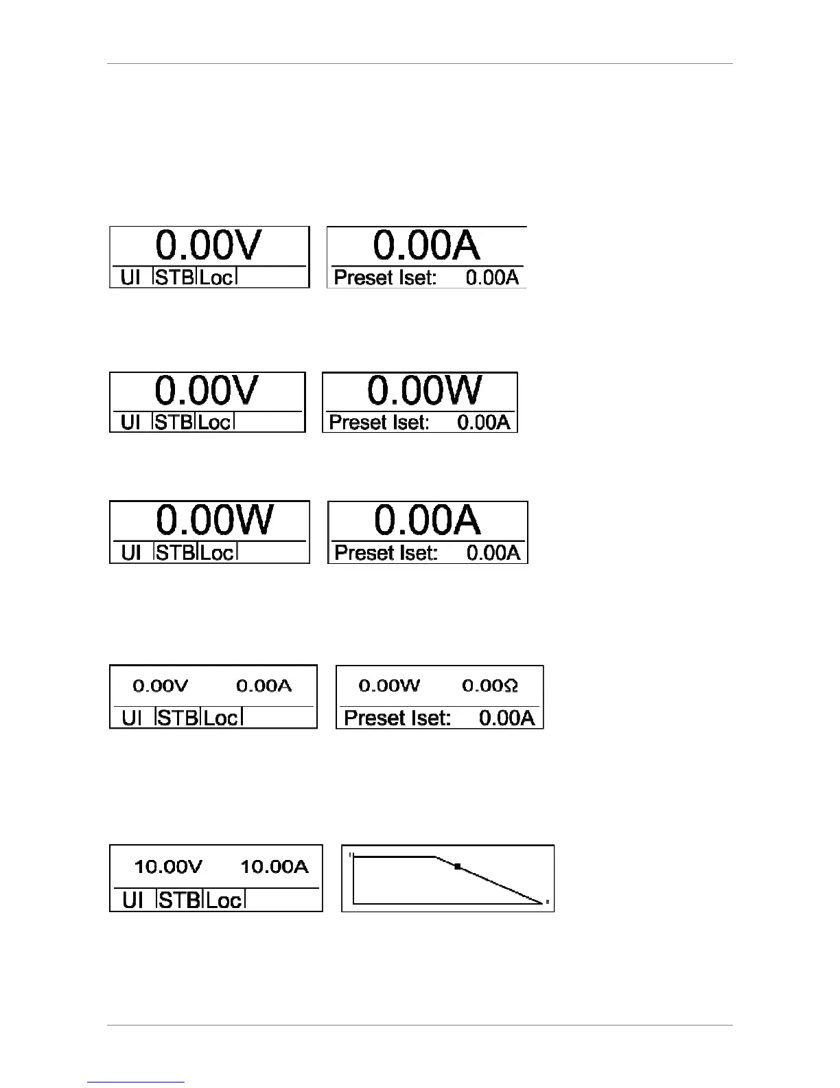
Main display overview
Main display 1
After power up, the display shows the actual output voltage and output current.
Main display 2
After pushing the button
Select
once, actual output voltage and output power are shown on the display.
Main display 3
After pushing the button
Select
twice, actual output power and output current are shown on the display.
Main display 4
After pushing the button
Select
thrice, actual output voltage and output current are shown on the left display and
actual output power (P = U
*
I) and load resistor (R = V ÷ C) are shown on the right display. The values for power and
resistor will be calculated from the actual values of the output voltage and the output current.
Main display 5/diagram screen
After pushing the button
Select
four times, actual output voltage and output current are shown on the left display.
The output characteristic of the power supply is shown on the right display. The X-axis shows the output voltage and
the Y-axis shows the output current.
The picture above shows the UIR mode of the power supply. The dot marks the actual operation point of the unit. The
diagram is always scaled for the maximum allowed output current (this value can be set in the setup menu (I
limit
)) and
the maximum allowed output voltage (this value can be set in the setup menu (U
limit
)).