Controller
42
Improper adjustment of the controller can lead to controller
oscillations which may damage connect ed devices!
C
ONTROLLER
S
TRUCTURE
PV
SIM
M
ODE AND
U
SER
M
ODE
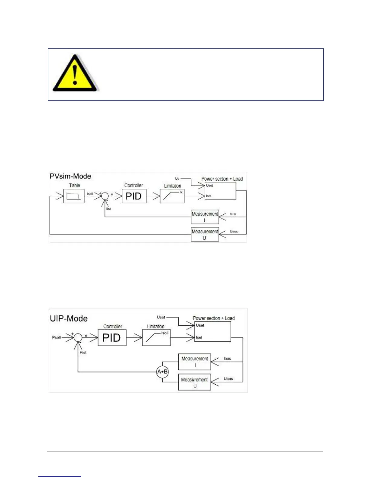
The current set point is calculated from the output voltage and a table. This set point stands for the input signal of the
PID controller after it was subtracted from the actual value. The PID controller releases the current set point for the
power supply. The current set point is limited to the short circuit current, as a maximum. The voltage set point of the
power supply is permanently set to the open circuit voltage of the table. In PVsim mode the current is regulated while
the voltage is fixed.
C
ONTROLLER
S
TRUCTURE
UIP
M
ODE
The output voltage is multiplied with the output current. The result is subtracted from the power set point. This signal
is the input signal of the PID controller, which releases the current set point for the power supply. The current set
point is limited to the current set point, as a maximum. The voltage set point of the power supply is permanently set
to the voltage set point. In UIP mode the current is regulated, while the voltage is fixed.
C
ONTROLLER
S
TRUCTURE
UIR
M
ODE
The measured output current is multiplied with the adjusted internal resistance. The result is subtracted from the
adjusted set point and is then the set point for the voltage controller:
U
soll
= U
set
- I
a
*
R
i