31
Chapter 2 Setup
2
Connectors on the DP-501
The DP-501 comes with the following connectors.
Setting the jumpers
Set the jumpers on the DP-501 as follows. (In the case of a Y connection, the jumpers may have any setting since
the connectors on the DP-501 are not used)
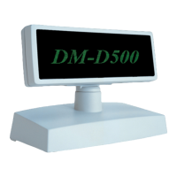
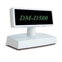
Attaching the customer display
The serial connector inside the DP-501 is attached using inch screws (hexagon nuts). If millimeter screws
are necessary, replace them with those supplied as accessories. Inch and millimeter screws can be distin-
guished based on whether the screw comes with a groove or not, as shown in the figure below.
JP1 JP2 Description
1-2 1-2 Set when connecting both the TM printer and stand for use.
Set in this way when using pass-through connection. (Default)
2-3 2-3 Set when using the customer display in a stand-alone connection,
without connecting a TM printer.
Set in this way when using stand-alone connection.
When connecting or disconnecting a cable, be sure the customer display and system are turned off.
DM-D connector
Connector for computer connection (RS-232)
Connector for power supply unit connection
Connector for power extension cable connection
Connector for printer connection (RS-232
 Loading...