65
Appendix A Hardware
Connectors
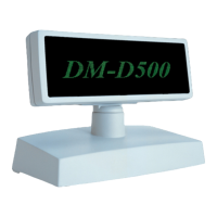
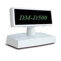
DM-D500 (Connector)
Pin assignments
Pin Num-
ber
Signal
Name
Signal
Direction
Signal Function
1FG- Frame ground
2 TXD Output (1) In a Y or pass-through connection (*1)
Transmit data to the printer
(2) In a stand-alone connection
Transmit data to the host
3 RXD Input Data received from the host computer
4 DSR Input Indicates whether or not the host computer or printer is ready to receive data.
(1) In a pass-through connection (*1)
[MARK] The printer is not ready to receive data
[SPACE] The printer is ready to receive data
(2) In a stand-alone connection
[MARK] The host computer is not ready to receive data
[SPACE] The host computer is ready to receive data
5 DTR Output Indicates whether or not the customer display is ready to receive data. (*2)
[MARK] The display is not ready to receive data
The display enters the MARK status in the following cases:
(1) During power-on initialization
(2) During self-test
(3) When the empty capacity of the receive buffer becomes 128 bytes or less (the
following case applies to pass-through connection only)
(4) When DSR enters the MARK status on printer selection
[SPACE] The display is ready to receive data
The display enters the SPACE status in the following cases:
(1) When power-on initialization finishes
(2) When self-test finishes
(3) When the empty capacity of the receive buffer recovers to 256 bytes or more from
128 bytes or less
6 SG - Signal GND
7 PS - Power supply terminal
8 PG - Return wire for power
(*1) Regarding pass-through connection and stand-alone connection, see Chapter 1.
(*2) When DTR signal is set to MARK status by the ESC/POS status confirmation command, this status is different from that where the
signal indicates whether or not the display is ready to receive data.
 Loading...