Perfection 4870 Photo Revision A
OPERATING PRINCIPLES Control Circuit 27
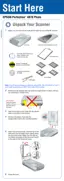
2.4 Control Circuit
2.4.1 Power Supply Circuit operation outline
The Control Circuit of this scanner consists of the following circuits.
Main Board
CCD Board
TPU Main Board
SUB_C Board
SUB_D Board
SUB_A Board (Power Button)
Switch: PS-132-B22PBS
SUB_B Board (LED: Built in the Lid TPU)
LED: ON/OFF LED (blue)
Panel Board (Start Button)
Switch : EVQPEE04M
LED : READY LED (green)
ERROR LED (red)
Power supply
220-240V: MPW0709
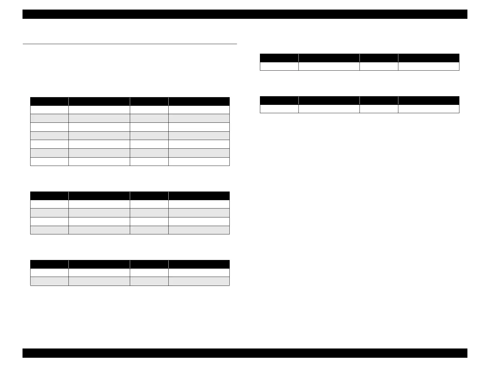
Table 2-3. IC Explanation
Location IC Location IC
IC1 A3957SLB-ATR IC8 ISP1581BD (GX)
IC2 A3957SLB-ATR IC9
K4S561632D-TC75000
IC3 AT93C46-10SI-1.8 IC10 74LVC138AD
IC4 UPC37M32 IC11 S80927CLMCGGX
IC5 E01A23EB IC12 74LVC02AD
IC6 MR27V402EJA IC13
K4S561632D-TC75000
IC7 AS7C31025-15TJC IC14 TSB43AA82APGE
Table 2-4. IC Explanation
Location IC Location IC
IC1 ILX183K IC5 NJU7665CF-TE1
IC2 BA178M05FP-E2 IC6 74HCT4053PW
IC3 AD9826KRS-REEL IC7 74ACT244
IC4 E02A41YA IC8 74ACT244
Table 2-5. IC Explanation
Location IC Location IC
IC1 A3957SLB-ATR IC3 74HCT595
IC2 A3957SLB-ATR IC4 74HCT595
Table 2-6. IC Explanation
Location IC Location IC
IC1 PSSI2021SAY IC2 PSS2021SAY
Table 2-7. IC Explanation
Location IC Location IC
IC1 PSSI2021SAY IC2 PSS2021SAY

 Loading...