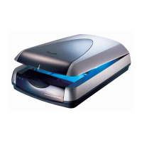
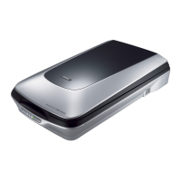
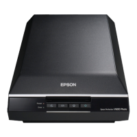
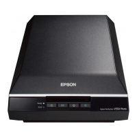
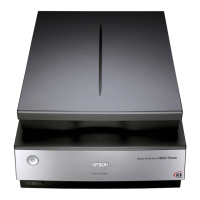
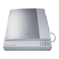
Perfection 4870 Photo Revision A
DISASSEMBLY/ASSEMBLY Disassembly Procedure 40
4.2 Disassembly Procedure
This section illustrates how to remove the main components of this product. Unless otherwise specified, the reassembly procedure is omitted here since the product can be reassembled
in the reverse order of the disassembly procedure. For the engagement of the main components, refer to the general exploded views in the Appendix.
The following flowchart shows the disassembling procedure step-by-step. When disassembling any unit, refer to the corresponding page number shown in the following figure.
Figure 4-2. Disassembly/Assembly Flowchart
Start
Removal of Document Cover
P.41
Removal of Upper Housing
P.42
Removal of Panel Board
P.43
Removal of Main Board
P.44
Removal of Carriage Unit
P.46
Removal of SUB_A Board
P.50
Removal of Power Supply
Cable Unit P.52
Removal of CR Motor Unit
P.48
Removal of Driven Pulley
P.49
Removal of TPU
Lower Housing P.53
Removal of TPU
Inverter Board P.54
Removal of TPU Main Board
P.57
Removal of Hinges
P.58
Removal of SUB_B Board
P.59
Removal of TPU CR Timing
Belt/ TPU Driven Pulley Unit
P.61
Removal of TPU Carriage Unit
P.56
Removal of TPU CR Motor
Unit/ TPU CR Motor Belt
P.59
Removal of TPU Unit Cable
P.62
Removal of Power Supply
Board P.51
 Loading...
