EasyManuals Logo

Epson RC700 User Manual

Epson RC700
316 pages
To Next Page IconTo Next Page
To Previous Page IconTo Previous Page
Page #176 background imageLoading...
Page #176 background image
Maintenance 7. Maintenance Parts Replacement Procedures
164 RC700 / RC700-A Rev.23
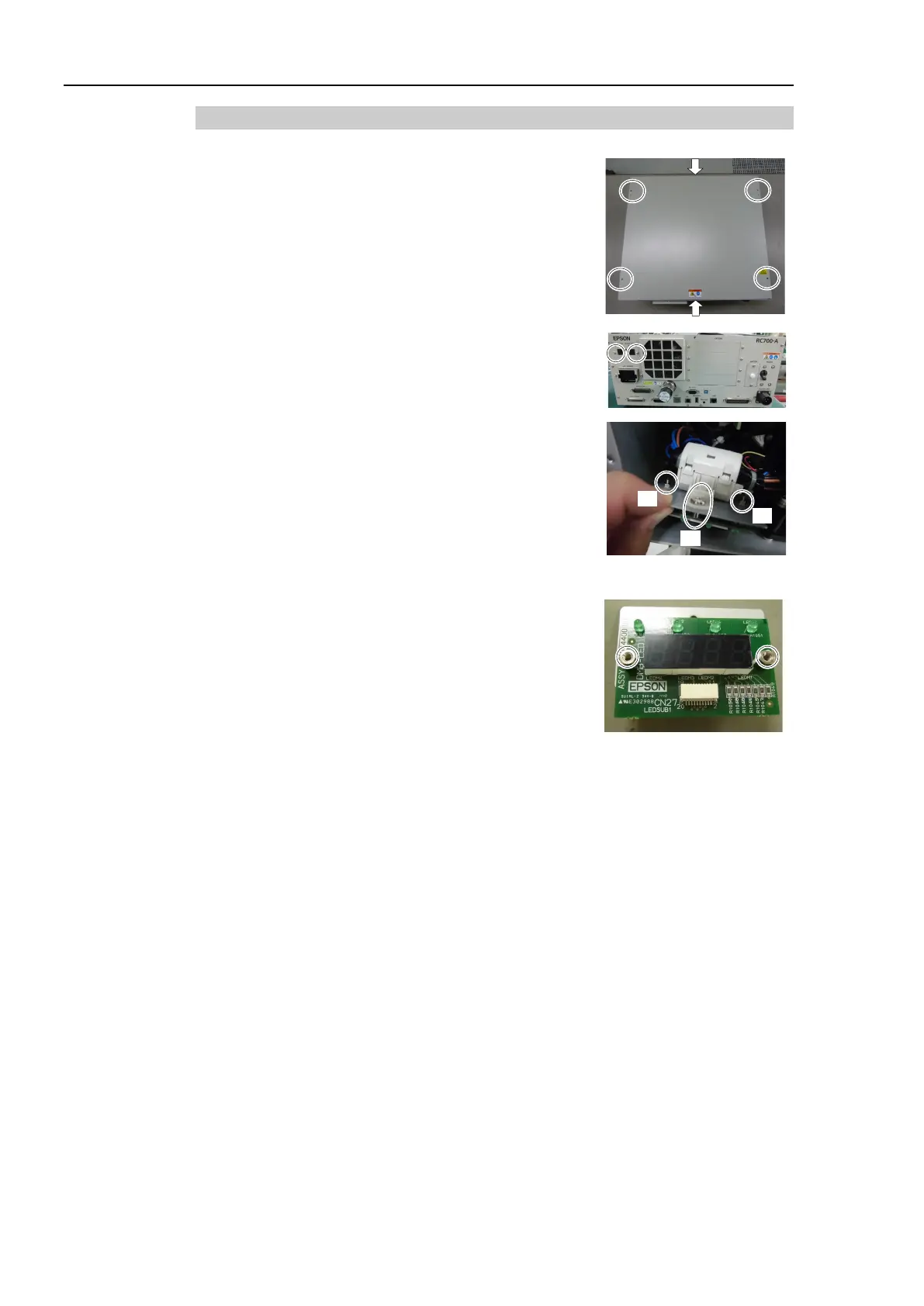
7.8.2 DMB-LED Board (RC700-A)
DMB
-LED Board
Removal
(RC700-A)
(1)
Turn
OFF the Controller.
(2)
Disconnect
the power plug.
(3)
Remove
the Top Panel. (Mounting screw ×6)
(4)
Remove the
DMB-LED board from the front panel.
(Mounting screw
×2)
(5)
Remove the ferrite core from the Support plate.
(Mounting screw
×1)
(5)
(7)
(7)
(6)
Disconnect the cables connected to the DMB
-LED
board.
(7)
Remove the
DMB-LED board from the support plate.
(
Nut ×2)
(8)
Remove the
stud bolt from the DMB-LED board.
(S
tud bolt ×4)
DMB
-LED Board
Installation
(RC700
-A)
(1)
Mount the
stud bolt to the DMB-LED board. (Stud bolt ×4)
(2)
Mount the
DMB-LED board to the support plate. (Nut ×2)
(3)
Connect the cable to the
DMB-LED board.
(4)
Mount the
ferrite core to the support plate. (Mounting screw ×1)
(5)
Mount the
DMB-LED board to the front panel. (Mounting screw ×4)
(6)
Mount the Top Panel. (Mounting screw
×6)
(7)
After connecting the power plug, turn on the Controller and check it works normally
without
vibration and abnormal sound.

Table of Contents

Questions and Answers:

Question and Answer IconNeed help?

Do you have a question about the Epson RC700 and is the answer not in the manual?

Epson RC700 Specifications

General IconGeneral
Maximum Axes16
Communication InterfacesEthernet, EtherNet/IP, PROFINET, PROFIBUS, CC-Link, RS-232C, USB
Safety StandardsISO 10218-1, ISO/TS 15066, IEC 61508, IEC 61511, ANSI/RIA R15.06
Operating SystemVxWorks
Power Supply24 VDC

Related product manuals