Safety 2. Part Names and Functions
14 RC700 / RC700-A Rev.23
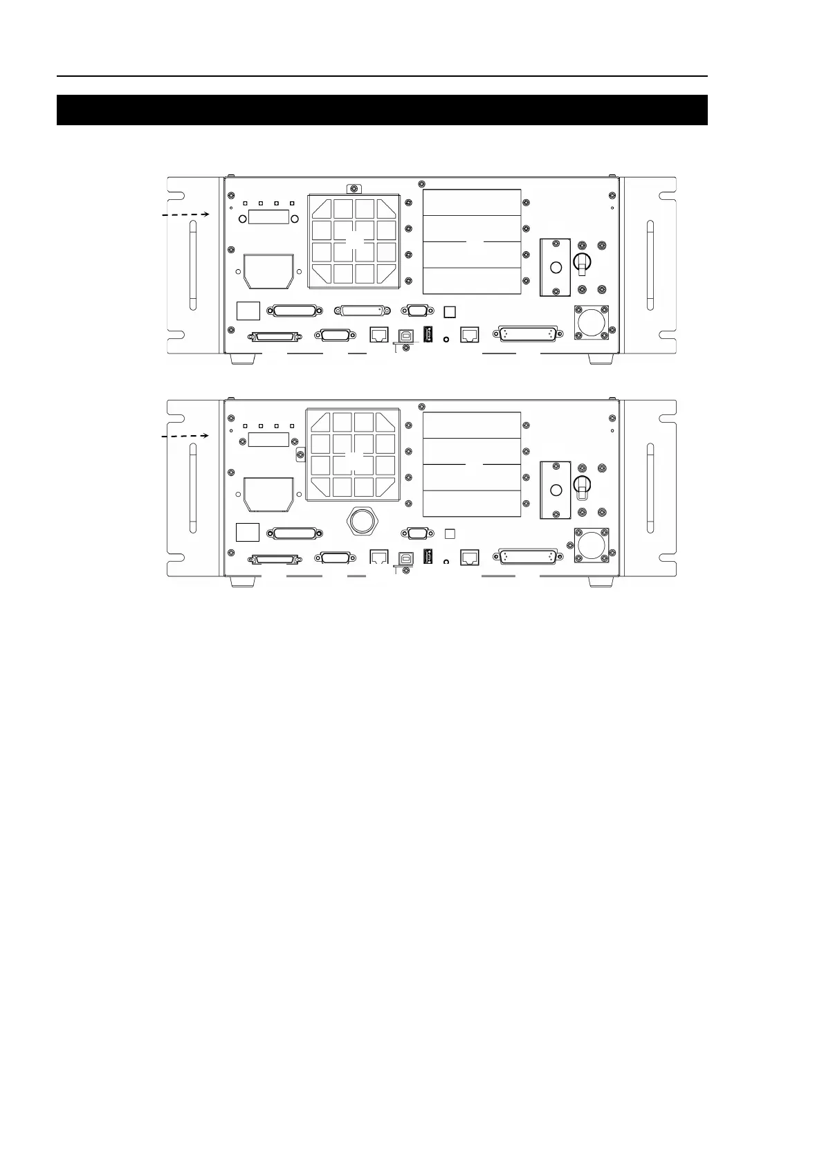
2. Part Names and Functions
RC700
RC700-A
(1) Controller Number label
The serial number of the Controller is indicated.
(2) LED
The LED indicates current operation mode
(TEST, TEACH, AUTO, or PROGRAM mode).
For details, refer to Setup & Operation 2.1 LED and Seven-segment LED.
(3) Seven-segment Display
Four-digit seven-segment LED displays the line number and the status of the
controller (error number, warning number, status of Emergency Stop and Safety
Door). For details, refer to Setup & Operation 2.1 LED and Seven-segment LED.
(4) M/C POWER connector
A connector for the Manipulator power source.
Connect the dedicated power cable attached to the Manipulator.
(5) Fan Filter
A protective filter is installed in front of the fan to filter out dust.
Check the condition of the filter regularly and clean it when necessary. A dirty filter
may result in malfunction of the robot system due to temperature rise of the
Controller.